SW series
1 /12Pages

SW series
1 /12Pages
Catalog excerpts

COMPONENTS Off-load Switch for Fixed Installation Title type SW
Open the catalog to page 1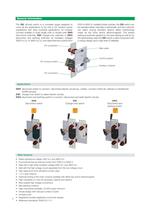
General information The SW off-load switch is a complete range designed to cover all the applications to be met in DC traction power substations and other industrial applications. Its modular concept enables to build single pole or double pole SWS disconnect switches, SWI change-over switches or SWG disconnect and earthing switches, for insulation voltages 3000 VDC/AC or 4800 VDC/AC and rated thermal currents from 2000 to 8000 A. Installed inside cubicles, the SW switch can be operated either manually or electrically, and the customer can select among standard options safety interlockings made...
Open the catalog to page 2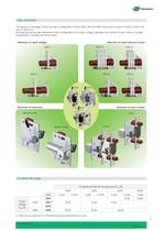
High modularity The figures on the page 2 show the basic configuration of each SWS, SWI and SWG device (for a current of 2000 A and a voltage of 1800 VDC). All these devices are also delivered in other configurations of current, voltage, operation and number of pole, thanks to a high industrialized modularity as shown below. Selection of rated voltage Selection of rated thermal current 8000 A 1800 V 3600 V 6300 A 2000 A SWS Selection of operation 4000 A SWG Selection of pole number SWI Manual mode 1 pole 2 pole Electric mode Complete SW range Conventional free air thermal current Ith [A] 2000...
Open the catalog to page 3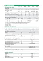
Data for product selection MAIN HIGH VOLTAGE CIRCUIT (1) At Tamb = +40°C and tested with high voltage connection according to standard IEC/EN 60943 (2) For specific values of the SWG earthing pole, refer to the figure and table of the page 5 LOW VOLTAGE AUXILIARY CIRCUIT Control circuit (motor and optional electromagnet lock) Nominal voltage Motor nominal closing/opening power Mechanical closing time (6) tc [s] Mechanical opening time (6) t0 [s] Electromagnet nominal power (DC and AC) [W] (6) For motorized version, at nominal control voltage = Un and Tamb = +20°C Auxiliary contacts for main circuit...
Open the catalog to page 4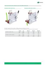
Peak and rated short-time withstand current of the SWG earthing pole Connection of earth cable on top Connection of earth cable on bottom The earth connection can be a cable or a exible connection according to the current. The values of the peak and rated short-time withstand current are depending on the position of the earth connection: - connection of earth on top: - connection of earth on bottom: Symbol INcwe ÎNcwe t Unit [kA] [kA] [s] SWG..20 14 20 0.25 SWG..40 28 40 0.25 SWG..63 28 40 0.25 INcwe ÎNcwe t [kA] [kA] [s] 14 20 0.25 14 20 0.25 28 40 0.25 5
Open the catalog to page 5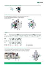
Details of the earth connection on the base plate 15 Ø1 1 15 Fixation system The SW series switches are xed vertically as shown here by means of M12 screws. The two or three xing supports must be in a at level to eachother. Examples of executions: SWI SWS-SWG Weights 1 pole SWS MA [kg]: ± 1 kg MO [kg]: ± 1 kg 18.20 9 12 18.40 12 15 18.63 16 20 1 pole SWI MA [kg]: ± 1 kg MO [kg]: ± 1 kg 18.20 14 16 18.40 20 23 MA [kg]: ± 1 kg MO [kg]: ± 1 kg 18.20 12 15 18.40 17 20 2 pole 36.20 11 14 36.40 15 18 36.63 20 23 18.20 17 20 18.40 24 27 18.63 28 35 18.63 27 30 18.20 24 28 18.63 21 25 18.20 22 27 36.20...
Open the catalog to page 9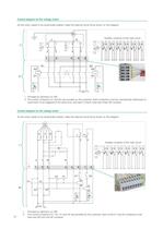
Control diagram for DC voltage motor As the motor needs to be dynamically braked, make the external circuit (II) as shown on this diagram. M J Auxiliary contacts of the main circuit K 3 1 3 1 4 2 4 2 1 2 3 I 2 4 A B 1 2 4 C 1 1 2 4 D 1 2 4 E 1 2 4 F 1 5 4 K1 K2 A2 A2 A1 + II 2 4 A1 + Un + I. Provided by Sécheron on SW. II. The control contactors K1 and K2 are provided by the customer. Both contactors must be mechanically interlocked to avoid them to be triggered at the same time; and each of them must have three NO contacts. Control diagram for AC voltage motor As the motor needs to be dynamically...
Open the catalog to page 10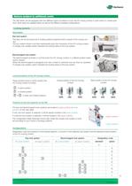
Options (subject to additional costs) The SW series can be equipped with two different types of systems to lock the HV moving contact in open and/or in closed posi- tions. Both types are detailed below as well as the different available configurations. Locking systems The keys can be removed only in locked positions (opened and/or closed) of the moving con- The key rotation drives a rod that mechanically locks the movement of the HV moving contact. A change-over auxiliary switch indicates the locking status of the lock system. Electromagnet lock system The electromagnet activates a rod that locks...
Open the catalog to page 11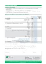
Designation code for ordering Designation code information • Be sure to establish the designation code from the latest version of our brochure by downloading it from the website: www.secheron.com. • Be careful to write down the 13 digits for the type designation code when placing your order. • It could be, for technical reasons, that some configurations of variants and options indicated in the designation code cannot be combined. • For other configurations not described in the brochure, please contact Sécheron. Designation code (options are subject to additional costs) - Order form Line Description...
Open the catalog to page 12All Secheron catalogs and technical brochures
 SPL
SPL8 Pages
 CONTACTOR RANGE Type SEC
12 Pages
 BMS15.18
8 Pages
 BMS15.002
3 Pages
 IS
IS8 Pages
 BW
BW10 Pages
 Pneumatic interlocking valve
4 Pages
 BTE03.04
8 Pages
 MMC
MMC2 Pages
 Wheel Flange lubricator
9 Pages
 Transformer - Rectifer Group
4 Pages
 MBS (IEEE/ANSI standards)
8 Pages
 MBS
MBS8 Pages
 SEPCOS
8 Pages
 MIU10
MIU102 Pages
 VM12
VM122 Pages
 VM10
VM102 Pages
 Short-circuit testing
4 Pages
 Substations in Containers
2 Pages
 Wayside Panels
2 Pages
 VLD
VLD4 Pages
 Inverter
4 Pages
 HPB45, HPB60
8 Pages
 UR15-44
4 Pages
 GB - G
9 Pages
 Master Controllers
8 Pages
 IS series
8 Pages
 BTE 03.04
8 Pages
 XMS 40.08
4 Pages
 BSV
BSV4 Pages
 RS series
8 Pages
 HSb
HSb4 Pages
 BMS 08_08
8 Pages
 UR6-31
12 Pages
 AC MODBOX®
2 Pages
 BVAC
BVAC4 Pages
 MACS
MACS8 Pages


- Single-pole switch
- Mechanical lock
- Spray tip
- Technology switch
- Liquid nozzle
- Circuit breaker
- Multipole switch
- Door lock
- Electromechanical switch
- Key lock
- Safety electric switch
- Multipole disconnect switch
- Safety lock
- Switchgear
- Current circuit breaker
- Voltage circuit breaker
- 3-pole switch disconnector
- Voltage switchgear