- Products
- Catalogs
- News & Trends
- Exhibitions
IS
1 /8Pages

IS
1 /8Pages
Catalog excerpts
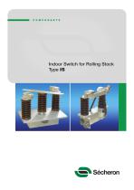
Indoor Switch for Rolling Stock Type IS
Open the catalog to page 1
The IS is a single pole off-load switch, electrically operated, and designed to be installed inside electric traction vehicles running on 25kVac and/or 15kVac networks. It is available in two main executions: disconnect switch or disconnect and earthing switch. Applications Indoor Switch for locomotives, trains and EMUs running on ac networks. Disconnect switch Application D Disconnect and earthing switch Application E Main features • Rated operational voltage 27.5 kVac • Rated free air thermal current 1000 A • Insulation level OV3 between poles and to earthed base plate • High rated short-time...
Open the catalog to page 2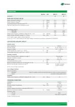
Technical data Application MAIN HIGH VOLTAGE CIRCUIT Rated operational voltage (1) Rated insulation voltage (1) Conventional free air thermal current (1,2) Peak and rated short-time withstand current Overvoltage category - Pole-pole - Pole-earth Rated power-frequency withstand voltage (50 Hz, 1 mn) Rated impulse withstand voltage (1.2 / 50 µs) (1) For higher values, please contact Sécheron (2) at Tamb=+40°C; test carried out with high voltage connections according to standards IEC/EN60943 LOW VOLTAGE AUXILIARY CIRCUIT Control circuit Type of operation Nominal voltage Range of voltage Control...
Open the catalog to page 3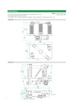
Main dimensions Weight: 32 kg for IS25.10D The maximum allowed flatness deviation of the support frame is 1 mm. 34 kg for IS25.10E HV and earth connections: M12 screws. The DIN-ISO 2768-1 coarse tolerances are applied to these dimensions. All dimensions are in mm. IS25.10D
Open the catalog to page 4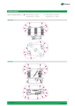
Isolating distance Minimum isolating distance:
Open the catalog to page 5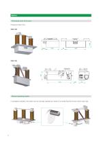
Protecting cover for LV part Protection index: IP2x Manual operating handle In emergency situation, the switch can be manually operated by means of a handle fixed at the end of the motor axle.
Open the catalog to page 6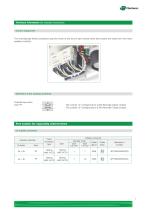
Technical information (for standard executions) Control equipment Two mechanically linked contactors stop the motor at the end of each stroke when they receive the order from the motor auxiliary contacts. Definition of the auxiliary switches Potential free switch Type: PF The contact “a” corresponds to a NO (Normally Open) contact. The contact “b” corresponds to a NC (Normally Close) contact. Part number for separately ordered items LV mobile connector Auxiliary switches Fixed connector type Mobile connector Number of pin Cable Cable Size Size entry 2.5 mm² 1.5 mm² gland Secheron's number
Open the catalog to page 7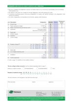
Designation code (options are subject to additional costs) - Order form • Be sure to establish the designation code from the latest version of our brochure by downloading it from the website: www.secheron.com. • Be careful to write down the 15 digits for the type designation code when placing your order. • It could be, for technical reasons, that some configurations of variants and options indicated in the designation code cannot be combined. • For other configurations not described in the brochure, please contact Secheron. Product type Rated operational voltage Rated conventional free air thermal...
Open the catalog to page 8All Secheron catalogs and technical brochures
 SPL
SPL8 Pages
 CONTACTOR RANGE Type SEC
12 Pages
 BMS15.18
8 Pages
 BMS15.002
3 Pages
 BW
BW10 Pages
 Pneumatic interlocking valve
4 Pages
 BTE03.04
8 Pages
 MMC
MMC2 Pages
 Wheel Flange lubricator
9 Pages
 Transformer - Rectifer Group
4 Pages
 MBS (IEEE/ANSI standards)
8 Pages
 MBS
MBS8 Pages
 SEPCOS
8 Pages
 MIU10
MIU102 Pages
 VM12
VM122 Pages
 VM10
VM102 Pages
 Short-circuit testing
4 Pages
 Substations in Containers
2 Pages
 Wayside Panels
2 Pages
 VLD
VLD4 Pages
 Inverter
4 Pages
 HPB45, HPB60
8 Pages
 UR15-44
4 Pages
 GB - G
9 Pages
 Master Controllers
8 Pages
 IS series
8 Pages
 SW series
12 Pages
 BTE 03.04
8 Pages
 XMS 40.08
4 Pages
 BSV
BSV4 Pages
 RS series
8 Pages
 HSb
HSb4 Pages
 BMS 08_08
8 Pages
 UR6-31
12 Pages
 AC MODBOX®
2 Pages
 BVAC
BVAC4 Pages
 MACS
MACS8 Pages


- Single-pole switch
- Mechanical lock
- Spray tip
- Technology switch
- Liquid nozzle
- Circuit breaker
- Multipole switch
- Door lock
- Key lock
- Electromechanical switch
- Safety electric switch
- Multipole disconnect switch
- Safety lock
- Switchgear
- Current circuit breaker
- Voltage circuit breaker
- 3-pole switch disconnector
- Voltage switchgear