- Products
- Catalogs
- News & Trends
- Exhibitions
BW
1 /10Pages

BW
1 /10Pages
Catalog excerpts
Type BWT and BWU Changeover Switches for Traction Motor Circuits The different circuit arrangements of the comm utator-type motors of electric traction vehicles are set up by change- over switches. These changeover - direction reversers, - motoring/braking changeover - converter or traction motor discon- nect switches, - series/parallel grouping switches, - power system selector switches or, - transformer tapchangers. In every case switching always takes place in the de-energized state and there are either two or three switch positions. The switches themselves are not designed as load switches...
Open the catalog to page 2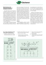
Changeover Switches Two of the most common uses of the changeover devices are for selecting either the motoring or braking circuit and for reversing the direction of travel. Figure 1 shows examples of how rotat- ing selector switches, contactors, cam- switch assemblies and linear switches perform these functions. Contactors or cam-switch assemblies are used when it is anticipated that residual currents will have to be interrupted. Contactors of type BMS/BPS are recommended For the sake of simplicity, the type are of the linear type. Figure 2a shows a basic circuit diagram of the device with two...
Open the catalog to page 3
Fig. 3 - Basic circuit diagram of a linear selector with three pneumatically controlled switch positions. Fig. 4 - Basic circuit diagram of a linear selector with two switch positions. Type BWU 15.08 changeover switch with a maximum of 14 levels and 5 rows of 4 moving contacts (vertical position). Fig. 5 - Contact unit for a type BWT/BWU changeover switch.
Open the catalog to page 4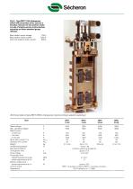
switch with pneumatic drive, used as a direction reverser for two traction motor circuits of shuttle-service motorcoaches operating on Swiss standard gauge Max. traction motor voltage 750 V Max. traction motor current 1050 A One-hour traction motor current 600 A Technical data of type BWT/BWU changeover devices (linear selector switches) Rated voltage Rated current Dynamic limit current Ambient temperature Mechanical lifetime Changeover time Drive voltage Pneumatic drive - operating pressure range Electro-motive drive Control switch 3 million switching operations BWT: 12 auxiliary contacts; BWU:...
Open the catalog to page 5
Fig. 7 - Assembly drawing of the type BWU 15.08 changeover switch. 1.1 = Optional compressed-air connection. 4.1 = Handle for manual operation. 5 = Contact units for main circuits, 5.1 = Fixed contacts with main power 5.2 = Contact unit in drive carriage. n = Number of contact levels. The changeover switches of each series differ in the maximum number of terminals they offer: The Table shows the technical data over switches. 3000 V) consist of the following, modu- - Contact modules comprising a linear contact unit and fixed contacts. - Drive carriages of variable length. - Control switch bank....
Open the catalog to page 6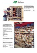
switch with electro-motive drive, used in the traction motor circuit of all-electric two-coach trainsets class Be 8/8 on the Forch line, Zurich (mounted horizontally beneath the coach floor). Rated traction motor voltage 1200 V Max. traction motor current 500 A One-hour traction motor current 350 A Fig. 9 - Main equipment unit of multi- purpose main-line locomotive Re 4/4 IV of the Swiss Federal Railways for oper- ation with single-phase a.c. at 15 kV/162/a Main equipment unit for the two dual-excited pulsating current traction motors of the driving bogie. The phase-angle controlled rectifier...
Open the catalog to page 7
Fig. 10 - Main equipment unit of class 250 multi-purpose main-line locomotive of Espaholes (RENFE) for operation with Main equipment unit for the d.c. series- wound dual traction motor (single-motor bogies) of the contactor-controlled vehicle. The locomotive is driven by pulsating current motors with rheostatic brakes separately Bank of electro-pneumatic contactors of type BPS (with arc chutes raised). Linear changeover switches of the following actuated motoring/braking selector switch. actuated direction reverser. One type BWT 30.08 manually actuated traction motor selector (disconnect switch)...
Open the catalog to page 8
Fig. 11 - Main equipment unit of class EL 1 main-line locomotive of the National Railways of Zimbabwe (NRZ) for operation with single-phase a.c. at 25 kV/50 Hz. would be capable of withstanding high short-circuit currents. Springs set the contact pressure to 46 + 5 N. Exact operation with greased contacts guar- antees resistance to mechanical wear. Such contact systems, however, have no breaking capacity, i.e. the contacts are only capable of interruptions in which there is no arc. The upper current limit is 500 mA; this demonstrates the changeover devices as selector swit- The switch is normally...
Open the catalog to page 9
- Heat tests - Mechanical tests involving up to three million switching operations without maintenance - Surge current tests in accordance The results of the tests came up to all expectations. Despite the lighter and more compact design of the newly developed changeover devices, it has been possible to achieve the high relia- bility for minimum wear required for traction applications, in which switch- ing is frequent. Previous experience has shown that when switches are assembled and maintained according to instructions and operating condi- tions are acceptable, there is practically The changeover...
Open the catalog to page 10All Secheron catalogs and technical brochures
 SPL
SPL8 Pages
 CONTACTOR RANGE Type SEC
12 Pages
 BMS15.18
8 Pages
 BMS15.002
3 Pages
 IS
IS8 Pages
 Pneumatic interlocking valve
4 Pages
 BTE03.04
8 Pages
 MMC
MMC2 Pages
 Wheel Flange lubricator
9 Pages
 Transformer - Rectifer Group
4 Pages
 MBS (IEEE/ANSI standards)
8 Pages
 MBS
MBS8 Pages
 SEPCOS
8 Pages
 MIU10
MIU102 Pages
 VM12
VM122 Pages
 VM10
VM102 Pages
 Short-circuit testing
4 Pages
 Substations in Containers
2 Pages
 Wayside Panels
2 Pages
 VLD
VLD4 Pages
 Inverter
4 Pages
 HPB45, HPB60
8 Pages
 UR15-44
4 Pages
 GB - G
9 Pages
 Master Controllers
8 Pages
 IS series
8 Pages
 SW series
12 Pages
 BTE 03.04
8 Pages
 XMS 40.08
4 Pages
 BSV
BSV4 Pages
 RS series
8 Pages
 HSb
HSb4 Pages
 BMS 08_08
8 Pages
 UR6-31
12 Pages
 AC MODBOX®
2 Pages
 BVAC
BVAC4 Pages
 MACS
MACS8 Pages


- Single-pole switch
- Mechanical lock
- Spray tip
- Technology switch
- Liquid nozzle
- Circuit breaker
- Multipole switch
- Door lock
- Key lock
- Electromechanical switch
- Safety electric switch
- Multipole disconnect switch
- Safety lock
- Switchgear
- Current circuit breaker
- Voltage circuit breaker
- 3-pole switch disconnector
- Voltage switchgear