- Products
- Catalogs
- News & Trends
- Exhibitions
BMS15.18
1 /8Pages

BMS15.18
1 /8Pages
Catalog excerpts

High power contactor Type BMS09.15 / BMS18.15 BMS09.18 / BMS18.18
Open the catalog to page 1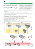
General information The BMS contactor, with other 100’000 units in operation worldwide, has always been a contactor valued by the car builders and operators of electric traction vehicles for its strong performance level and its extremely high reliability. variants and options that enable our customers to find the most appropriate version to fit their application, either as a stand-alone contactor, or delivered coupled with a Sécheron dedicated pre-charging contactor type PCC18. Power contactor modules, convenient to order and easy to install, are a frequent wish of our customers. Sécheron brings...
Open the catalog to page 2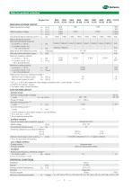
Data for product selection Symbol Unit MAIN HIGH VOLTAGE CIRCUIT 900 900 1’800 Rated operational voltage Ue [VDC ] 1’800 Ue [VAC ] 2’300 2’300 2’300 Rated insulation voltage Ui [VDC ] 2’300 Ui [VAC ] 1’500 1’800 1’500 1’800 1’500 1’800 1’500 1’800 Conventional free air thermal current (1) Ith [A] Rated operational current/ Electrical operational frequency 1’500/C1 1’800/C1 1’500/C1 1’800/C1 1’500/C1 1’800/C1 1’500/C1 1’800/C1 - dc current, τ = 15 ms Ie [A] - ac current, cos Φ = 0.8 1’500/C2 1’800/C2 (16.7, 25 & 50/60 Hz) Ie [A] 15 / 100 Rated short-time withstand current Icm / t [kA]/[ms] 20...
Open the catalog to page 3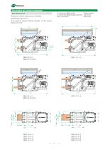
Information for product integration Dimensions without tolerances are indicative. All dimensions are in mm. The maximum allowed flatness deviation of the support frame is 0.5 mm. LV connectors (BMS control) : Wago terminal LV connectors (BMS auxiliary switches) : M3 screws Earth connections : M6 screws Main dimensions
Open the catalog to page 4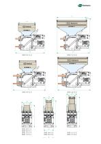
WAGO minal
Open the catalog to page 5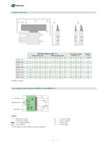
Insulation distances Insulating distances table (mm) With earthed wall With insulating wall A B C D A B C D Arc chute removal distance (mm) Low voltage control diagram for BMSxx.15 and BMSxx.18 Legend : Sécheron’s scope : Customer’s scope : Low voltage interface : Coil controller (1) Un : power supply dc UEF : Control voltage (1) k0 : Supply relay k1 : Control relay Control voltage (UEF) can be different from supply voltage (Un).
Open the catalog to page 6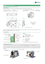
Options (subject to additional costs) Integrated pre-charging contactor (PCC18) Main dimensions All dimensions are in mm. The maximum allowed flatness deviation of the support frame is 0.5 mm. LV connections (PCC18 auxiliary switches) : M3 screws HV connections (PCC18) : M6 screw Earth connection : Through BMS LV connections (PCC18’s coil) WAGO terminals : HV The drawings hereabove represent the PCC18 when mounted on any BMS..15/18 versions. The other dimensions of the BMS..15/18 indicated in page 4, 5 and 6 remain valid. Control diagram 5 : Sécheron’s scope : Customer’s scope : Low voltage WAGO...
Open the catalog to page 7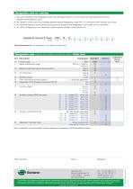
Designation code for ordering • Be sure to establish the designation code from the latest version of our brochure by downloading it from the website: www.secheron.com • Be careful to write down the complete alphanumerical designation code with 15 characters when placing your order. • For technical reasons some variants and options indicated in the designation code might not be combined. • For other configurations not described in the brochure, please contact Secheron. Example of customer’s choice: Line: The bold characters of the designation code define the device type. Designation code (options...
Open the catalog to page 8All Secheron catalogs and technical brochures
 SPL
SPL8 Pages
 CONTACTOR RANGE Type SEC
12 Pages
 BMS15.002
3 Pages
 IS
IS8 Pages
 BW
BW10 Pages
 Pneumatic interlocking valve
4 Pages
 BTE03.04
8 Pages
 MMC
MMC2 Pages
 Wheel Flange lubricator
9 Pages
 Transformer - Rectifer Group
4 Pages
 MBS (IEEE/ANSI standards)
8 Pages
 MBS
MBS8 Pages
 SEPCOS
8 Pages
 MIU10
MIU102 Pages
 VM12
VM122 Pages
 VM10
VM102 Pages
 Short-circuit testing
4 Pages
 Substations in Containers
2 Pages
 Wayside Panels
2 Pages
 VLD
VLD4 Pages
 Inverter
4 Pages
 HPB45, HPB60
8 Pages
 UR15-44
4 Pages
 GB - G
9 Pages
 Master Controllers
8 Pages
 IS series
8 Pages
 SW series
12 Pages
 BTE 03.04
8 Pages
 XMS 40.08
4 Pages
 BSV
BSV4 Pages
 RS series
8 Pages
 HSb
HSb4 Pages
 BMS 08_08
8 Pages
 UR6-31
12 Pages
 AC MODBOX®
2 Pages
 BVAC
BVAC4 Pages
 MACS
MACS8 Pages


- Single-pole switch
- Mechanical lock
- Spray tip
- Technology switch
- Liquid nozzle
- Circuit breaker
- Isolator switch
- Multipole switch
- Door lock
- Key lock
- Electromechanical switch
- Safety electric switch
- Multipole disconnect switch
- Safety lock
- Switchgear
- Current circuit breaker
- Voltage circuit breaker
- 3-pole switch disconnector
- Voltage switchgear