

Guide to 17th Edition Testing

Guide to 17th Edition Testing
The document provides guidance on testing electrical installations in accordance with the 17th Edition of the IEE Wiring Regulations (BS 7671:2008). It stresses the importance of inspecting and testing installations during erection and upon completion to ensure compliance with safety standards.
- Continuity of Protective Conductors: Ensures all bonding conductors are connected to the supply earth, with low resistance readings indicating proper connections.
- Continuity of Ring Final Circuit Conductors: Verifies that line, neutral, and protective conductors form a continuous path, with specific resistance values confirming correct wiring.
- Insulation Resistance: Confirms no current paths exist between conductors when loads are disconnected, ensuring sufficient insulation.
- Polarity: Verifies correct connection of single-pole switches and socket outlets to the line conductor.
- Earth Electrode Resistance: Confirms the earth electrode provides a satisfactory path to earth using various testing methods.
- Earth Fault Loop Impedance: Measures the impedance of the earth fault loop to ensure it is within safe limits.
- RCD Testing: Ensures Residual Current Devices operate correctly to provide protection against earth faults.
- Continuity Testing: Detailed procedures for testing continuity of circuit protective conductors.
- Insulation Resistance Testing: Procedures for measuring insulation resistance between various conductors.
The document highlights advancements in installation testing technology, emphasizing the benefits of using modern testers like the PowerPlus 1557, which streamline processes, reduce costs, and improve efficiency.
Seaward's software solutions facilitate less paperwork and hassle, allowing for efficient data management and certificate generation.
The document underscores the necessity of adhering to testing procedures to ensure electrical safety and compliance with regulations. It also provides practical guidance on using testing equipment and software to enhance testing efficiency.
- Three measurements are taken by moving the potential spike P2 to different positions relative to the earth electrode and current spike C2. The average of these measurements is calculated, and if the percentage deviation exceeds 5%, the test should be repeated with a larger separation between the current spike and the earth electrode.
- It is crucial to disconnect the earth electrode from the installation to avoid errors due to parallel earth paths.
- Some instruments, like the Seaward ERT 1557, use an external current clamp to measure current through the earth electrode, eliminating the need to disconnect the electrode from the installation.
- The earth fault loop impedance (Zs) is calculated by measuring at the furthest point and adding the resistance of the line and earth conductors (R1+R2).
- Preparation involves switching off the main switch and disconnecting the main earthing conductor.
- RCDs should be tested for tripping times at various current levels to ensure proper functionality.
- Insulation resistance tests verify electrical isolation between conductors and earth, using a test instrument capable of producing specific DC test voltages.
- Continuity testing ensures a current-carrying path exists, using a test instrument with specific voltage and current requirements.
- The PowerPlus 1557 is a combined test and inspection unit with built-in 17th Edition certificates, allowing for comprehensive testing and data recording.
- It supports Bluetooth data transfer and certificate printing.
This lightweight resistance tester is suitable for use on 110V, 230V, and three-phase electrical systems. It provides accurate earth electrode resistance measurement without the need to disconnect the electrode and can also measure soil resistivity. The device supports 2, 3, and 4-wire measurement methods, making it one of the most competitive earth resistance testers available.
- Current clamp measurement
- Earth resistance measurement
- Battery powered
- PC download capability
- Storage for up to 500 records
- 2, 3, or 4-wire measurement
PowerGuard Pro 2 is comprehensive certificate software ideal for creating test and inspection certificates. It allows users to capture and store test information and produce professional certificates that comply with Part-P and 16th/17th Edition Regulations. PowerGuard Pro Mobile 2 enhances flexibility by enabling certificate information entry directly into a PDA.
- Easy set-up wizard
- Auto validation
- Email PDF certificates
- Create certificate templates
- Certificates check in/out
Catalog excerpts
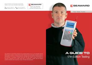
Seaward, Bracken Hill, South West Industrial Estate, Peterlee, County Durham, SR8 2SW United Kingdom Tel: +44 (0) 191 586 3511 Fax: +44 (0) 191 586 0227 Email: [email protected] Web: www.seaward.co.uk Seaward, Clare, Rigel Medical, Cropico, Seaward Group USA are all part of the Seaward Group Tried. Tested. Trusted. 17th Edition Testing AGuideto This material is for information purposes and as general guidance only. It is not necessarily deemed definitive and is subject to change without notice. Seaward and its associated companies accept no responsibility for any errors or consequential loss or damage which may arise from misinterpretation of the information or procedures. However, every effort has been made to ensure the accuracy of information presented but the reader should refer to manufacturer / supplier data and relevant published standards when producing or using 17th Edition test procedures.
Open the catalog to page 1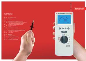
02 - 03 The Installation System 04 Introduction 04 - 09 A. Tests before the supply is connected 05 1. Continuity of protective conductors including main and supplementary equipotential bonding 06 2. Continuity of ring final circuit conductors 07 3. Insulation resistance 08 4. Polarity 09 5. Earth electrode resistance 12 - 14 B. Tests with the electrical supply connected 12 1. Earth fault loop impedance 13 - 14 2. RCD testing 14 - 17 Appendix 14 1. Continuity testing 15 - 17 2. Insulation resistance testing 18 - 19 PowerPlus 1557 20 - 21 17th Edition product range Tried. Tested. Trusted. Contents...
Open the catalog to page 2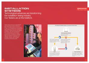
Installation systems Technological advances are transforming the installation tesing industry. Our Testers are at the forefront. 3 Tried. Tested. Trusted. Today’s world moves at an unprecedented pace. Everything’s smarter, smaller and faster. This is good news for us, and for you. It means we’re developing and manufacturing better equipment and we can now help your business or institution become more efficient and effective. We call it PowerSolutions. This comprehensive process involves everything from choosing your installation tester and software,to following up with calibration services. It...
Open the catalog to page 3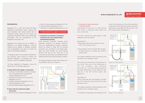
i. Continuity of circuit protective conductors (CPC) The purpose of this test is to verify that the CPC forms a continuous path around the circuit under test. The test is carried out (using either or both methods shown) as follows: Test Method 1: a) Temporarily link the line conductor to the CPC in the Consumer Unit. b) Test between the line and the CPC at each accessory point e.g. a ceiling rose, switch or socket outlet. The reading obtained at each accessory point should be a low resistance value. The resistance measured at the extremity of the circuit is the sum of the resistances of the line...
Open the catalog to page 4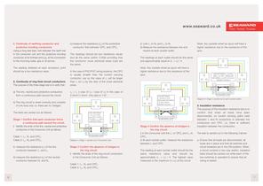
ii) Link L1 to N2 and L2 to N1 iii) Measure the resistance between line and neutral at each socket outlet. The readings at each outlet should be the same and approximately equal to (r1 + rn) / 4. Note: Any sockets wired as spurs will have a higher resistance due to the resistance of the spur. Diagram 5: Stage 2 (carried out in Consumer Unit) Stage 3 Confirm the absence of bridges in the ring circuit. i) In the Consumer Unit link L1 to CPC2 and L2 to CPC1. ii) At each socket outlet, measure the resistance between L and CPC. The reading at each socket outlet should be the same resistance value...
Open the catalog to page 5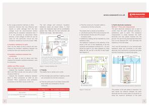
c) That the correct pin of socket outlets is connected to the line conductor. The polarity test is carried out as follows : i) Link the line and the CPC in the Consumer Unit. ii) Test between the line and CPC at each accessory point. A satisfactory reading will be indicated by a low resistance value. The resistance measured at the extremity of the circuit is the sum of the resistances of the line conductor and protective conductor (R1 + R2) and should be equal to the value obtained by using Tables 9A, 9B, and 9C in the IEE On-site Guide. See Diagram 8. Diagram 8: Polarity Test 5. Earth electrode...
Open the catalog to page 6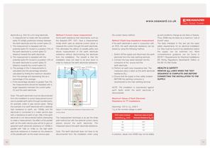
the current clamp method. Method 3 Earth loop impedance measurement If the earth electrode is used in conjunction with an RCD, the earth electrode resistance can be tested by using the following method. i. Switch off the supply and disconnect the earth electrode from the main earthing terminal. ii. Connect the loop tester between the line conductor at the source and the earth electrode. iii. Perform an earth loop impedance test. The measured value is taken as the earth electrode resistance (RA). iv. Ensure that the supply is then safely isolated BEFORE the earthing conductor is reconnected to...
Open the catalog to page 7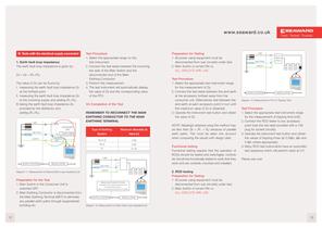
13 Tried. Tested. Trusted. B. Tests with the electrical supply connected 1. Earth fault loop impedance The earth fault loop impedance is given by: Zs = Ze + (R1+R2) The value of Zs can be found by: I. measuring the earth fault loop impedance Zs at the furthest point II. measuring the earth fault loop impedance Ze at the incoming supply and adding (R1+R2). III. taking the earth fault loop impedance Ze provided by the distributor and adding (R1+R2). Diagram 11: Measurement of External Earth Loop Impedance Ze Preparation for the Test 1. Main Switch in the Consumer Unit is switched OFF. 2. Main Earthing...
Open the catalog to page 8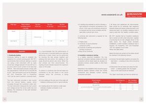
If all lamps and appliances are disconnected, there should be an extremely high resistance between phase and neutral, phase and earth, and neutral and earth. An insulation resistance test is used to verify that this 'healthy' condition exists. BS 7671 requires that an insulation resistance test is carried out with a test instrument capable of producing the dc test voltages shown in the table below. For single phase domestic installations, a 500V insulation resistance test is required. the PowerPlus 1557 and PowerTest 1557 are capable of such tests. Please see table below. Before the tests are...
Open the catalog to page 9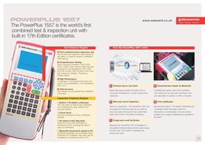
19 Tried. Tested. Trusted. Powerplus 1557 www.seaward.co.uk The PowerPlus 1557 is the world’s first combined test & inspection unit with built-in 17th Edition certificates. Test Features Keypad First combined test & inspection unit Record test and inspection data directly on the tester, no need for paper or additional PDA devices. Comprehensive Testing Earth continuity, Insulation (100V, 250V, 500V, 1000V), High current & Non-trip loop impedance, Line Impedance, PFC, PSC, RCD trip current, RCD trip time, RCD Auto test sequence, Voltage / Frequency, Phase rotation. High Performance 4 readings...
Open the catalog to page 11All Seaward catalogs and technical brochures
 PV150+
3 Pages
 Seaward NTB-1
2 Pages
 D255
D2552 Pages
 PrimeTest 100
2 Pages
 Solar Survey 100/200R Series
4 Pages
 PrimeTest 50
2 Pages
 00 Series
2 Pages
 2018 Seaward PAT Selector
15 Pages
 Cropico DO4000 Series
2 Pages
 Cropico DO4A
2 Pages
 SDR Series
1 Page
 Printers and Scanners
8 Pages
 PR11
PR112 Pages
 MTS
MTS2 Pages
 HAL Series
5 Pages
 HAL LED
4 Pages
 CR Series
1 Page
 Apollo+ Series
6 Pages
 Seaward Manufacturing
12 Pages
 PATGuard 3 PAT Testing Software
153 Pages
 PrimeTest 250+ PAT Tester
4 Pages
 Apollo 600
5 Pages
 PrimeTest 250+
4 Pages
 Apollo 400
5 Pages
 Powercheck 1557
2 Pages
 Power Clamp
3 Pages
 Apollo 500
20 Pages
 Cropico RS3 Datasheet
2 Pages
 Cropico RM6 Datasheet
1 Page
 Cropico RBC Datasheet
2 Pages
 Cropico RBB Datasheet
2 Pages
 Cropico CM5-N Datasheet
1 Page
 Cropico RM8 Datasheet
1 Page
 Cropico RM6N Datasheet
1 Page
 Cropico DO7010 Datasheet
2 Pages
 Cropico DO7Plus Datasheet
2 Pages
 Cropico DO6 Datasheet
2 Pages
 Cropico DO7E Datasheet
2 Pages
 Cropico DO7 Datasheet
2 Pages
 PowerCheck 1557 Datasheet
2 Pages
 PAT Checkbox Datasheet
2 Pages




Archived catalogs
 IRT 1557 Datasheet
2 Pages
 Clare A252 Datasheet
1 Page
 PATGuard Elite 2 Datasheet
2 Pages
 PowerGuard Pro 2 Datasheet
2 Pages
 PowerPlus 1557 Datasheet
2 Pages
 PowerGuard Pro Mobile 2
2 Pages
 Type L Plus Datasheet
2 Pages
 Proving Units Datasheet
2 Pages
 Clare A320 Datasheet
2 Pages
 PrimeTest 250 Datasheet
2 Pages
 Clare HAL Combi Datasheet
2 Pages
 Clare Sentinel Datasheet
2 Pages
 Clare PowerSmart Datasheet
2 Pages
 Clare B255 Datasheet
2 Pages
 SEN60204 Datasheet
22 Pages
 Halo Hook Datasheet
2 Pages
 VT800D Datasheet
2 Pages
 ERT 1557 Datasheet
2 Pages
 VT800 Datasheet
2 Pages
 PrimeTest 350 Datasheet
2 Pages
 PATGuard Pro 2
2 Pages
 PATGuard Elements Datasheet
2 Pages
 PowerTest 1557 Datasheet
2 Pages
 SD 300 Datasheet
2 Pages
 Clare Horizon II Datasheet
2 Pages
 PrimeTest 300 Datasheet
2 Pages
 Cropico DO8000 Datasheet
2 Pages
 Clare Elite Datasheet
4 Pages
 Clare B433R Datasheet
2 Pages
 Calibrationhouse
2 Pages
 Clare G2000 Datasheet
2 Pages
 Seaward PAT Testing Guide
20 Pages
 Clare Product
28 Pages
 ClareHAL
12 Pages
 Cropico Product
48 Pages
 PAT Testing Product
20 Pages
 Seaward Product
72 Pages
 Powerplus 1557
4 Pages
 Cropico DP6 Datasheet
2 Pages
 Supernova Elite
2 Pages
 PATGuard Lite 2
2 Pages
 Test n Tag Datasheet
2 Pages
 Supernova Plus Datasheet
2 Pages
 DM800/DM800R
1 Page
 Europa Plus PAT Tester
2 Pages
 Supernova Plus PAT Tester
2 Pages


- Seaward electrical cable
- Analysis software solution
- Seaward power cable
- Process software
- Windows software
- Calibration system
- Seaward portable tester
- Battery charger
- Seaward digital tester
- Seaward automatic tester
- Industrial tester
- Seaward automatic testing device
- Seaward voltage tester
- Reporting software
- Industrial printer
- Benchtop tester
- Seaward portable detector
- Black electrical cable
- Fuse box
- Manual test equipment