- Catalogs
- Scienta Omicron
- VT SPM_2012
VT SPM_2012
1 /20Pages

VT SPM_2012
1 /20Pages
Catalog excerpts
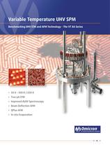
Variable Temperature UHV SPM Benchmarking UHV STM and AFM Technology - The VT XA Series • 50 K – 500 K / 650 K • True pA STM • Improved dI/dV Spectroscopy • Beam Deflection AFM • QPlus AFM • In-situ Evaporation
Open the catalog to page 1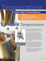
VT Series: Major Product Releases: 1994 VT STM 1998 VT with Beam Deflection AFM 2003 Sub-pA STM & improved spectroscopy 2008 VT with QPlus AFM Variable Temperatures After a period of rapid development, Scanning Probe Microscopy (SPM) has become a standard analysis technique in surface science. The Omicron VT SPM is the established microscope in many research labs. It won the prominent R&D 100 award in 1996 and to the present day more than 500 instruments have been delivered and successfully installed around the world. The design concept and ultimate performance as well as the concept of easy...
Open the catalog to page 3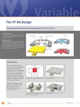
Heating and Cooling Concept for Temperatures from 50 K to 650 K The thermal connection (copper braid) between flow cryostat and sample stage is fixed and thermally isolated from the microscope stage. An embedded solid-state heater element in the sample stage allows indirect radiative heating of samples. The stage is equipped with a temperature sensor to measure the sample temperature. A temperature range between 50 K and 500 K is possible. Instruments without cooling option can heat the sample up to 650 K. Sample Plates using standard Omicron samples plates. The pilosophy with many different...
Open the catalog to page 4
The VT-series enables the mounting of up to two EFM evaporators on the VT-chamber for in-situ materials growth even during imaging. The Omicron patented piezo inertia drive allows the same sample area to be relocated and imaged even after the sensor has been retracted during evaporation. Before Evaporation After Evaporation surface, image size: 80 nm x Data courtesy: M. Hupalo and M. C. Tringides, Dept. of Physics Iowa State Univ., Ames Lab. USDOE, USA, PHYSICAL REVIEW B, VOLUME 65 Easy and Safe Sensor Exchange 1) The transfer plate is inserted into the sample stage to pick up a sensor using...
Open the catalog to page 5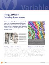
True pA STM and Tunneling Spectroscopy All instruments of the VT series are equipped with state-of-the-art STM and STM spectroscopy capabilities. It is possible to extend this with AFM functionality, and the VT instruments can be used either with Beam Deflection AFM, the ‘QPlus‘ AFM, or with both types of AFM. Capacitive compensation Bias current compensation Frequency select / Low pass 330 nA range: 80 kHz / 3 kHz 3 nA range: 800 Hz / 200 Hz IT monitor, direct IT Offset compensation 100 nm Growth of multilayer ice films and the formation of cubic ice imaged with STM at IT = 0.4 pA. Ice films...
Open the catalog to page 6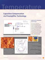
Capacitive Compensation via Preamplifier Technology Optimized for Modulation Spectroscopy Internal switch (Software controlled) R1 Sample R1 = 3 GΩ 3 nA Range R2 = 30 MΩ 330 nA Range R2 Sensor-sample intrinsic (floating) - capacitance IT + UMod (AC) UGap (DC) Internal capacitive compensation Schematic of VT-series pre-amplification and internal capacitive compensation. 6 with sub-monolayer coverage obtained in the low-current mode. Set-point values IT = 2.5 pA, UGap = 1.4 V. The white and black dotted circles highlight the first polymer layer and a partially nucleated second layer, respectively....
Open the catalog to page 7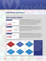
Non-Contact Modes Non-contact mode Non-Contact Operation Modes: The sensor is forced to oscillate or is excited to oscillate at its resonance frequency (eigenfre- quency). There are two basic modes of operation; amplitude modulation (AM) and frequency modulation (FM). FM is the pre- ferred mode in-vacuum, as the quality factors of the sensors (q-factors) are typically higher than in air. Magnetic Force Microscopy (MFM): Non-contact AFM can be used to measure magnetic forces. The magnetic dipole interac- tion is recorded at a constant tip-sample distance. The typical distance between tip and surface...
Open the catalog to page 8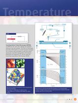
Lock-in amplifier PI-feedback ~ Low-pass filter Frequency demodulator Tip height control + SKPM Sample Polymer Source Insulator Gate U=UDC+UAC sin (2π f2t) Id Vq z (nm) Scanning Kelvin Probe Microscopy (SKPM): In SKPM an AC and a DC voltage are applied between tip and sample. The lock-in technique provides information on work function changes on a surface and correlates it with the simultaneously recorded topography information. Detection at frequency 2f2 can be used for Scanning Capacitance Microscopy (SCM). Drain Vd 200 Source 0 Drain 0V 0 Vd -1 V -2 V -3 V -4 V -5 V -6 V -7 V -8 V Vt (V) -2...
Open the catalog to page 9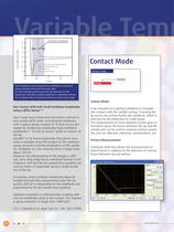
Oscillation amplitude 3 Fts(z) (nN), It(z) (nA) 2 1 0 -1 Contact Mode Short-range force (Morse potential) -2 Long-range (νdW) force Total force -3 Contact mode Tunneling current 0 0.5 1 z (nm) 1.5 2 Plot of tunnelling current and typical force potentials as a function of Sample distance between surface and front sensor atom. For AFM, interaction involves many more tip atoms than for STM. Shaded area: small QPlus oscillation amplitudes in combination with specific df setpoints allow for tuning the sensitivity to various force ranges. Contact Mode: Non-Contact AFM with Small Oscillation Amplitudes...
Open the catalog to page 10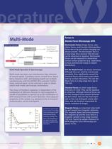
Forces in Atomic Force Microscopy AFM Multi-Mode Multi-mode operation Normal forces FN Deflection Lateral forces FL detection Δ f frequency shift Excitation Amplitude regulation Sample It detection Damping Tunneling current IT Multi-Mode Operation & Spectroscopy: Multi-mode operation uses simultaneous data collection of several signals. Tunnelling current, normal force, lateral force, frequency shift, and damping signals are available simultaneously with the MATRIX SPM controller. Furthermore, external inputs can be selected in order to obtain useful multi-mode spectroscopy combinations. The...
Open the catalog to page 11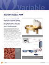
Beam Deflection AFM The classical Beam Deflection AFM method uses a microscale cantilever with a sharp tip at its end. The cantilever is typically silicon or silicon nitride with a tip radius curvature on the order of several nanometers. The force interaction between the tip and the sample surface leads to a deflection of the cantilever. In a Beam Deflection AFM the deflection is measured using a laser spot reflected from the top surface of the cantilever into an array of photodiodes. Depending on the application it is possible to operate in the static contact mode or in the dynamic non contact...
Open the catalog to page 12All Scienta Omicron catalogs and technical brochures
 NanoESCA
4 Pages
 UHV Suitcase
2 Pages
 ARPES-Lab
4 Pages
 Cryo Manipulators
2 Pages
 XPS-Lab
2 Pages
 Fermi DryCool SPM
8 Pages
 TESLA JT SPM
8 Pages
 EFM Evaporators
8 Pages
 Argus CU
7 Pages
 UHV NANOPROBE
12 Pages
 Fermi SPM
8 Pages
 Leonova Diamond
8 Pages
 Leonova Emerald
12 Pages
 Intellinova
4 Pages
 MULTIPROBE
8 Pages
 Omicron EFM V05
8 Pages
 PRO-75/100 MBE Systems
2 Pages
 EVO-25/50 MBE Systems
2 Pages
 LAB-10 MBE System
2 Pages
 ISE 5
ISE 52 Pages
 EKF 300
2 Pages
 Omicron CN 10 V02
2 Pages
 MBD-LEED
8 Pages
 FOCUS PEEM
16 Pages
 Argus
Argus12 Pages
 MULTISCAN Lab
2 Pages
 LT NANOPROBE
8 Pages
 UHV STM 1
2 Pages
 Cryogenic STM & SFM
4 Pages
 SPHERA
8 Pages
 NanoSAM Lab
6 Pages


Archived catalogs
 VT SPM
11 Pages
 LT STM_2017
16 Pages
 ESCA+_2010
8 Pages
 LT STM_2012
16 Pages
 MATRIX SPM Control System
8 Pages
 EFM 2
EFM 28 Pages
 CMA 100
4 Pages
 NanoESCA
8 Pages
 SPECTALEED
8 Pages
 SPM PROBE
2 Pages
 EKF 1000
2 Pages
 Multiscan STM
2 Pages
 MS5 & Control Unit
2 Pages
- Liquids analyzer
- Spectrometer
- Integration analyzer
- Laboratory microscope
- Compact analyzer
- Laboratory spectrometer
- Desktop microscope
- Spectrum analyzer
- Process evaporator
- Process spectrometer
- High-resolution spectrometer
- Laboratory evaporator
- Lamp illumination
- Compact illumination
- UV illumination
- Ergonomic microscope
- 3D microscope
- R&D spectrometer
- Modular microscope