- Catalogs
- Schweitzer Engineering Laboratories
- SEL-487B Bus Differential and Breaker Failure Relay
- Company
- Products
- Catalogs
- News & Trends
- Exhibitions
SEL-487B Bus Differential and Breaker Failure Relay
1 /32Pages

SEL-487B Bus Differential and Breaker Failure Relay
1 /32Pages
Catalog excerpts
SEL-487B Bus Differential Relay Busbar and Breaker Failure Protection, Automation, and Control System Major Features and Benefits The SEL-487B Relay provides bus current differential protection, circuit breaker failure protection, and backup overcurrent protection. The relay has 21 analog current inputs and three analog voltage inputs. For buses with no more than seven terminals, use one SEL-487B in a single-relay application. For buses with eight to ten terminals, use two SEL-487B relays. For buses with as many as 21 terminals, use three SEL-487B relays; each relay provides as many as six independent and adaptable zones of protection. Contact SEL Research and Development for methods on protecting larger systems. ➤ Busbar differential protection operates in less than one cycle to increase system stability margins and reduce equipment damage. ➤ Flexible zone selection and six differential zones provide protection for multiple busbar applications. ➤ Failed CT detection elements reliably indicate open and shorted CTs for alarming and/or blocking. ➤ Differential protection accommodates as high as 10:1 CT ratio mismatch without auxiliary CTs. ➤ Differential protection is secure for external faults with minimal CT requirements. ➤ Breaker failure protection for each terminal integrates bus and breaker failure protection. ➤ Instantaneous and inverse time-overcurrent elements provide backup protection for each terminal. ➤ Negative- and zero-sequence over- and undervoltage elements provide for differential element supervision. ➤ Three dedicated check zones are available in each relay to supervise complex bus differential schemes. ➤ Interconnection with automation systems uses IEC 61850 or DNP3 protocols directly or DNP3 through a Communications Processor. Use FTP for high-speed data collection. Schweitzer Engineering Laboratories, Inc.
Open the catalog to page 1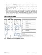
The relay records a wide range of system events with sampling rates as fast as 8 kHz, and as much as 24 seconds of data per COMTRADE compliant event report. ➤ Parallel Redundancy Protocol (PRP) provides seamless recovery from any single Ethernet network failure, in accordance with IEC 62439-3. The Ethernet network and all traffic are fully duplicated with both copies operating in parallel. ➤ IEEE 1588, Precision Time Protocol version 2 provides high-accuracy timing over an Ethernet network. ➤ Time-domain link (TiDL) technology allows for remote data acquisition through use of the SEL-2240 Axion....
Open the catalog to page 2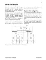
Protection Features Order the 9U chassis version of the SEL-487B to equip the relay with a maximum of four interface boards. With four interface boards, the relay has a total of 103 inputs (72 common inputs and 31 independent inputs) and 40 outputs (24 high-speed, high-current interrupting outputs and 16 standard outputs). Order the 7U chassis version of the SEL-487B to equip the relay with a maximum of two interface boards. With two interface boards, the relay has a total of 55 inputs (36 common inputs and 19 independent inputs) and 24 outputs (12 high-speed, high-current interrupting outputs...
Open the catalog to page 3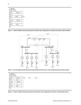
=>>ZONE <Enter> BUS PROTECTION Rinadel Station Terminals in Protection HELIUM SILICON Bus-Zones in Protection NORTH Terminals in Protection BORON ARGON Bus-Zones in Protection EAST Terminals in Protection SILICON KRYPTON Bus-Zones in Protection SOUTH Terminals in Protection SODIUM NEON Bus-Zones in Protection WEST =>> Boron Lithium LITHIUM =>>ZONE <Enter> BUS PROTECTION Rinadel Station Terminals in Protection HELIUM SILICON Bus-Zones in Protection NORTH EAST Terminals in Protection SILICON KRYPTON Bus-Zones in Protection SOUTH Terminals in Protection SODIUM NEON Bus-Zones...
Open the catalog to page 4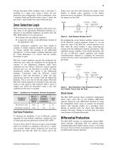
Closing disconnect DS2 combines Zone 1 and Zone 2, resulting in a single zone. Figure 4 shows the new protection zone configuration. In this combination, Zone 1 includes North and East bus-zones. Figure 5 shows the new Zone 1 that includes bus-zones North and East. Zone Selection Logic Busbar protection requires assignment of the correct current values to the appropriate differential elements as a function of user-defined conditions. To achieve this, the SEL-487B employs a two-step process: ► Evaluates the user-defined conditions. ► Assigns the currents to the differential element of the appropriate...
Open the catalog to page 5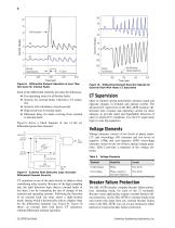
Fault Inception –50 Current (Amps) Current (Amps) –5 Internal Fault Detection Figure 8 Differential Element Operation in Less Than One Cycle for Internal Faults Each of the differential elements provides the following: ➤ Fast operating times for all busbar faults ➤ Security for external faults with heavy CT saturation ➤ Security with subsidence current present ➤ High sensitivity for busbar faults ➤ Minimum delay for faults evolving from external to internal faults Figure 9 shows a block diagram of one of the six differential protection elements. CT Supervision Current Input I01 Trip Output Figure...
Open the catalog to page 6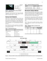
Table 4 Overcurrent Elements per Terminal ® Disconnect Switch Starts to Close © Disconnect Switch Starts to Open Figure 12 Disconnect Switch Auxiliary Contact Requirements for the Zone Selection Logic; No CT Switching Required Schweitzer Engineering Laboratories, Inc.
Open the catalog to page 7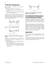
Tie-Breaker Configurations Figure 13, Figure 14, and Figure 15 show three tiebreaker schemes: ➤ Two CTs configured in overlap (Figure 13) ➤ A single CT with two cores configured in overlap (Figure 14) ➤ Two CTs configured with a differential element across the breaker (Figure 15) Configure any one of these schemes without using external auxiliary relays. Figure 13 and Figure 14 also show the tie breaker closing onto an existing fault, F1. The SEL-487B includes tie-breaker logic to prevent the loss of both zones for this fault. T 87 Figure 15 Two CTs Configured With a Differential Element Across...
Open the catalog to page 8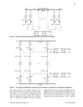
Single SEL-487B Protecting Double Bus Sections With Bus Tie Breaker Two Single SEL-487B Relays Protecting the Two Busbars in a Breaker-and-a-Half Busbar Configuration For stations with 10 to 21 terminals (Figure 18), use three separate SEL-487B relays and wire analog current inputs from A-, B-, and C-phases separately into each relay. This way, each of the 21 analog current inputs in each relay measures only one phase, with six dedicated zones of protection available. Each relay operates Schweitzer Engineering Laboratories, Inc. independently; the only communication among relays is MIRRORED BITS®...
Open the catalog to page 9All Schweitzer Engineering Laboratories catalogs and technical brochures
 SEL-C662
1 Page
 2019 CATALOG
248 Pages
 2018 CATALOG
374 Pages
 METERING ACCESSORIES CATALOG
20 Pages
 STANDARD CABINET CATALOG
28 Pages
 SEL-3622 Security Gateway
12 Pages
 SEL-710-5 Motor Protection Relay
28 Pages
 SEL-3610 Port Server
12 Pages
 2017 SEL Catalog
373 Pages
 SEL-2664 Field Ground Module
12 Pages
 SEL-2533 Annunciator
12 Pages
 SEL-2414 Transformer Monitor
20 Pages
 SEL-2244 Digital I/O Module
8 Pages
 SEL-2243 Power Coupler
4 Pages
 SEL-2242 Chassis/Backplane
8 Pages
 SEL-2240 Axion®
32 Pages
 SEL-1102 Computing Platform
12 Pages


Archived catalogs
 2015 Modern Solutions Catalog
331 Pages
 SEL 2008 Product Catalog EOS Mfg
44 Pages


