
Catalog excerpts

FIELD DEVICES - FLOW Product Specifications Foxboro® Model IMT31A Magnetic Flow Signal Converter The IMT31A magnetic flow signal converter can be used with 8400A, 8500A, 9500A, 9600A and 9700A magnetic flow sensors. ► Extended accuracy option ► Diagnostics of device and application ► Certified for use in hazardous areas
Open the catalog to page 1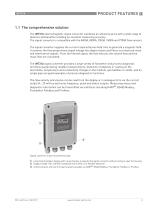
1.1 The comprehensive solution The IMT31A electromagnetic signal converter combines an attractive price with a wide range of features and benefits including an excellent measuring accuracy. The signal converter is compatible with the 8400A, 8500A, 9500A, 9600A and 9700A flow sensors. The signal converter supplies the current required by two field coils to generate a magnetic field. It converts the flow proportional signal voltage into digital values and filters out electrical noise and interference signals. From the filtered signal, the flow velocity, the volume flow and the mass flow are...
Open the catalog to page 3
nPRODUCT FEATURES Highlights • For operation with the 8400A, 8500A, 9500A, 9600A and 9700A flow sensors • For flow sensors over a diameter range from DN2.5 up to DN1200 • Housing in aluminium with a polyester topcoat or in stainless steel (option) • Tropicalized electronics to protect it from humidity (option) • Available outputs: 4...20 mA current output, pulse/frequency output, status output/limit switch and Ex i I/O (option) • HART® as standard • Communication to third party systems via HART ®, Foundation Fieldbus, Profibus PA/DP or Modbus • Control input option • Power supply via...
Open the catalog to page 4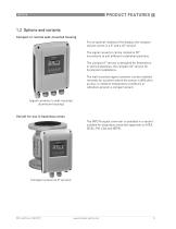
1.2 Options and variants Compact or remote wall-mounted housing For an optimal reading of the display, the compact variant comes in a 0° and a 45° version. The signal converter can be rotated in 90° increments to suit different installation positions. The compact 0° version is designed for flowmeters in vertical pipelines, the compact 45° version for horizontal installations. The wall mounted signal converter can be installed remotely for locations where the sensor is difficult to access, or ambient temperature conditions or vibrations prevent a compact variant. (signal converter in...
Open the catalog to page 5
nPRODUCT FEATURESStainless steel housing (option) Whereas the standard housing material is aluminium with a polyester topcoat, the IMT31A can optionally be ordered in a stainless steel housing. The robust housing is suitable for many applications in the food and beverage industry. It is designed for environments where extreme chemicals or aggressive cleaning are used. The housing is dual rated to IP67/69 protection category to resist wash down cleaning and no glass is used for the display window. The mounting angle for the compact housing and the rounded edges in the wall-mount position...
Open the catalog to page 6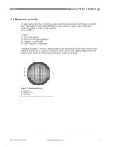
1.3 Measuring principle An electrically conductive fluid flows inside an electrically insulated pipe through a magnetic field. This magnetic field is generated by a current, flowing through a pair of field coils. Inside of the fluid, a voltage U is generated: U=v*k*B*D in which: v = mean flow velocity k = factor correcting for geometry B = magnetic field strength D = inner diameter of flowmeter The signal voltage U is picked off by electrodes and is proportional to the mean flow velocity v and thus the flow rate Q. A signal converter is used to amplify the signal voltage, filter it and...
Open the catalog to page 7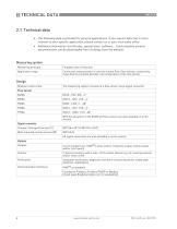
2 TECHNICAL DATA 2.1 Technical data • The following data is provided for general applications. If you require data that is more relevant to your specific application, please contact us or your local sates office. • Additional information [certificates, special tools, software,...) and complete product documentation can be downloaded free of charge from the website.
Open the catalog to page 8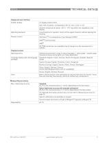
TECHNICAL DATA 2 Display and user interface
Open the catalog to page 9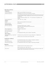
2 TECHNICAL DATA Operating conditions
Open the catalog to page 10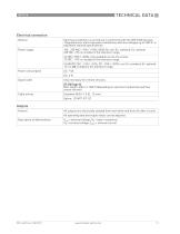
TECHNICAL DATA 2Electrical connection General
Open the catalog to page 11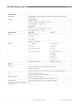
2 TECHNICAL DATA Current output
Open the catalog to page 12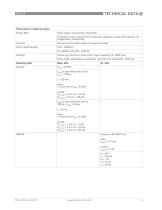
TECHNICAL DATA 2 Pulse output / frequency output
Open the catalog to page 13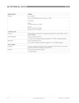
2 TECHNICAL DATA Operating data
Open the catalog to page 14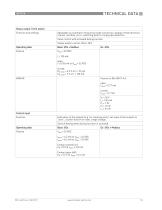
TECHNICAL DATA 2 Status output / limit switch
Open the catalog to page 15
2 TECHNICAL DATA PROFIBUS DP
Open the catalog to page 16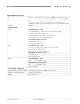
TECHNICAL DATA 2Approvals and certificates CE
Open the catalog to page 17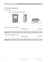
2.2 Dimensions and weight 2.2.1 Housing Wall-mounted version, aluminium housing Dimensions and weights in mm and kg Dimensions [mm] a Wall-mounted version Dimensions and weights in inch and lb Dimensions [inch] a Wall-mounted version
Open the catalog to page 18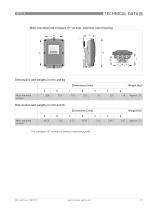
TECHNICAL DATA 2 Wall-mounted and compact 10° version, stainless steel housing The compact 10 version is without mounting plate.
Open the catalog to page 19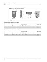
Dimensions and weights in inch and lb
Open the catalog to page 20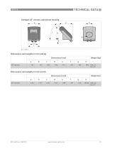
Compact 45° version, aluminium housing Dimensions and weights in mm and kg Dimensions [mm] a 45° version Dimensions and weights in inch and lb Dimensions [inch] a 45° version
Open the catalog to page 21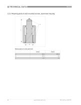
2 TECHNICAL DATA2.2.2 Mounting plate of wall-mounted version, aluminium housing Dimensions in mm and inch
Open the catalog to page 22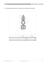
TECHNICAL DATA 22.2.3 Mounting plate of wall-mounted version, stainless steel housing
Open the catalog to page 23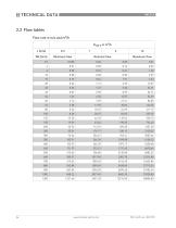
2 TECHNICAL DATA2.3 Flow tablesFlow rate in m/s and m3/h
Open the catalog to page 24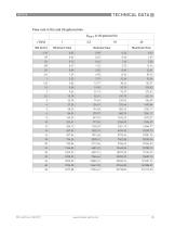
TECHNICAL DATA 2 Flow rate in ft/s and US gallons/min
Open the catalog to page 25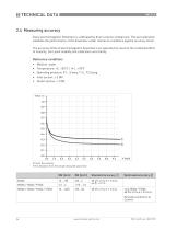
2 TECHNICAL DATA 2.4 Measuring accuracy Every electromagnetic flowmeter is calibrated by direct volume comparison. The wet calibration validates the performance of the flowmeter under reference conditions against accuracy limits. The accuracy limits of electromagnetic flowmeters are typically the result of the combined effect of linearity, zero point stability and calibration uncertainty. Reference conditions • Medium: water • Temperature: +5...+35°C / +41...+95°F • °perating pressure: CU...5 barg / 1.5...72.5 psig • Inlet section: > 5 DN • Outlet section: > 2 DN X [m/s]: flow velocity Y...
Open the catalog to page 26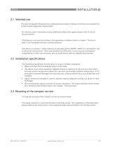
3.1 Intended use The electromagnetic flowmeters are designed exclusively to measure the flow and conductivity of electrically conductive, liquid media. For devices used in hazardous areas, additional safety notes apply; please refer to the Ex documentation. If the device is not used according to the operating conditions (refer to chapter "Technical data"), the intended protection could be affected. This device is a Group 1, Class A device as specified within CISPR11:2009. It is intended for use in industrial environment. There may be potential difficulties in ensuring electromagnetic...
Open the catalog to page 27All Schneider Electric catalogs and technical brochures
-
CFT34A
2 Pages
-
IMT30A
2 Pages
-
15607
2 Pages
-
IMV25
2 Pages
-
Evolis 24kV catalogue
80 Pages
-
NEX 24 catalogue 2010
56 Pages
-
ICatalogue CT VT
52 Pages
-
Fuses catalogue 2012
24 Pages
-
RM6 Catalogue
76 Pages
-
Catalogue Human Machine Interfaces
150 Pages
-
Osiswitch XCK_N catalogue
16 Pages
-
Catalogue Osisense XG
26 Pages


