
- Catalogs
- Schneider Electric
- Foxboro® Model 9500A Magnetic Flow Sensor

- Products
- Catalogs
- News & Trends
- Exhibitions
Foxboro® Model 9500A Magnetic Flow Sensor

Foxboro® Model 9500A Magnetic Flow Sensor
The Foxboro Model 9500A Magnetic Flow Sensor is designed for water and wastewater applications, compatible with IMT30A, IMT31A, and IMT33A converters. It features a robust, fully welded construction suitable for potable water, wastewater, and industrial water applications.
- Reliable for groundwater, potable water, and sewage applications.
- Durable fully welded construction with no moving parts.
- Available in diameters from DN25 to DN2000, with DN3000 on request.
- Rugged liners approved for drinking water and suitable for subsoil installation.
- Bi-directional flow metering and extensive diagnostic capabilities.
- Uses Faraday's law of induction for measuring electrically conductive fluids.
- Primary measure is flow velocity; volume flow is secondary.
- Available in compact and remote versions with various signal converters.
- High accuracy with repeatability of ±0.1% of the measured value.
- Operating temperature ranges from -5°C to +90°C depending on liner material.
- Pressure ratings vary by diameter and standard, with negligible pressure loss.
- Easy installation with flanged design and standard ISO insertion lengths.
- IP68 rated for installation in flooded measurement chambers.
- Electrical connections include standard and optional cables, with a maximum length of 600 meters.
- CE marked, fulfilling EU directives.
- ATEX and FM certified for hazardous areas, with specific classifications for different versions.
Approvals for liners include NSF/ANSI standard 61, ACS, KTW, DVGW-W270, and WRAS. Protection category is IP66/67 with an option for IP68. Shock and vibration tests are conducted as per IEC standards.
Flowmeters are calibrated by direct volume comparison. Accuracy limits are influenced by linearity, zero point stability, and calibration uncertainty. Pressure derating graphs and vacuum load capacities are specified for various materials and diameters.
Details for remote and compact versions include tables for nominal sizes, dimensions, and weights in metric and imperial units.
Guidelines emphasize avoiding vibrations and magnetic fields, ensuring proper inlet and outlet pipe sections, and maintaining correct mounting positions. Torque and pressure specifications are included.
Safety instructions highlight disconnecting power before working on connections. Grounding requirements and the virtual reference option for the IMT33A flow converter are explained.
Lists model descriptions and nominal diameters with corresponding liner materials.
Lists sizes of hard rubber components and nominal pressures according to standards like EN 1092-1, ASME B 16.5, and JIS.
Details on explosion-proof versions include EEx zone 1 and 2, FM Class I DIV 2, and various EAC certifications.
Options include compact and separate configurations with aluminum or stainless steel housings.
Models include IMT31A and IMT33A in various configurations.
Lining options include PFA and hard rubber. Electrodes are available in stainless steel, Hastelloy C4, Titanium, and Hastelloy C22.
Materials include steel and stainless steel, with specific DIN standards.
Protection classes include IP 66/67 and IP 68.
Cable options include lengths up to 100 m. Calibration options include standard and specific tag plates.
Instructions include providing model number, flow data, calibration information, and optional selections.
Mentions the FlowExpertPro sizing application and other Foxboro products, with contact information for Schneider Electric Systems USA, Inc.
Catalog excerpts

FIELD DEVICES - FLOW Product Specifications Foxboro® Model 9500A Magnetic Flow Sensor The 9500A magnetic flow sensor can be used with IMT30A, IMT31A and IMT33A magnetic flow converters. ► For all water and wastewater applications ► Wide range of approvals for potable water ► Robust, fully welded construction Foxboro by Schneider Electric
Open the catalog to page 1
5 Model code 6 Notes
Open the catalog to page 2
1.1 Reliable solution for the water and wastewater industry The 9500A is designed to meet the demands for all water and waste water applications including groundwater, potable water, waste water, sludge and sewage, industry water and salt water. The 9500A has a field proven and unsurpassed lifetime. This is assured by the fully welded construction, full bore pipe, absence of moving parts and wear resistant liner materials. The sensor has the widest diameter range available in the market: from DN25 up to DN2000 (DN3000 available on request). 1 Robust fully welded construction 2 Diameter range:...
Open the catalog to page 3
nPRODUCT FEATURES Highlights • Rugged liners suitable for any water and wastewater application • Proven and unsurpassed lifetime, huge installed base • Tamper proof, fully welded construction, also available in customer specific constructions • Drinking water approvals including KTW, KIWA, ACS, DVGW, NSF, WRAS • Suitable for subsoil installation and constant flooding (IP68) • Bi-directional flow metering • Standard in house wet calibration of sensors up to diameter DN2000 • Easy installation and commissioning • No grounding rings with virtual reference option on IMT33A • Extensive diagnostic...
Open the catalog to page 4
PRODUCT FEATURESD1.2 Options The reliable solution for the water and wastewater industry From standard to customized For easy ordering the standard range of the 9500A covers all popular sizes, flange materials and connections (ASME, EN, JIS, AWWA). The 9500A is designed to meet the demands for all water and waste water applications including groundwater, potable water, waste water, sludge and sewage, industry water and salt water. The 9500A has a field proven and unsurpassed lifetime assured by the fully welded housing, full bore pipe construction, absence of moving parts and wear resistant liner...
Open the catalog to page 5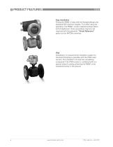
Easy installation Fitting the 9500A is easy with the flanged design and standard ISO insertion lengths. To further ease the operation, the 9500A can be installed without filters and straighteners. Even grounding rings are not required with the patented "Virtual Reference" option on the IMT33A converter. IP68 Installation in measurement chambers subject to (constant) flooding is possible with the IP68 rated version. The chambers can even be completely surpassed if the IP68 version is combined with our special subsoil coating, allowing the 9500A to be installed directly in the ground.
Open the catalog to page 6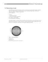
1.3 Measuring principle An electrically conductive fluid flows inside an electrically insulated pipe through a magnetic field. This magnetic field is generated by a current, flowing through a pair of field coils. Inside of the fluid, a voltage U is generated: U=v*k*B*D in which: v = mean flow velocity k = factor correcting for geometry B = magnetic field strength D = inner diameter of flowmeter The signal voltage U is picked off by electrodes and is proportional to the mean flow velocity v and thus the flow rate Q. A signal converter is used to amplify the signal voltage, filter it and convert...
Open the catalog to page 7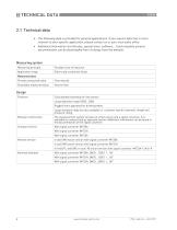
2 TECHNICAL DATA 2.1 Technical data • The following data is provided for general applications. If you require data that is more relevant to your specific application, please contact us or your local sates office. • Additional information [certificates, special tools, software,...) and complete product documentation can be downloaded free of charge from the website.
Open the catalog to page 8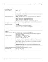
TECHNICAL DATA 2Measuring accuracy Reference conditions
Open the catalog to page 9
2 TECHNICAL DATA Pressure
Open the catalog to page 10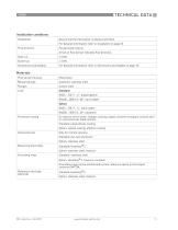
TECHNICAL DATA 2Installation conditions Installation
Open the catalog to page 11
2 TECHNICAL DATAProcess connections Flange
Open the catalog to page 12
TECHNICAL DATA 2Approvals and certificates CE This device fulfils the statutory requirements of the EU directives. The manufacturer certifies successful testing of the product by applying the CE mark.
Open the catalog to page 13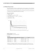
2 TECHNICAL DATA 2.2 Measuring accuracy Every electromagnetic flowmeter is calibrated by direct volume comparison. The wet calibration validates the performance of the flowmeter under reference conditions against accuracy limits. The accuracy limits of electromagnetic flowmeters are typically the result of the combined effect of linearity, zero point stability and calibration uncertainty. Reference conditions • Medium: water • Temperature: +5...35°C / +41...95°F • °perating pressure: M...5 barg / 'I.5...72.5 psig • Inlet section: > 5 DN • Outlet section: > 2 DN Optionatty for IMT30A and IMT31A;...
Open the catalog to page 14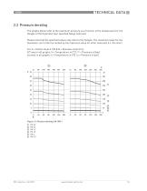
2.3 Pressure derating The graphs below refer to the maximum pressure as a function of the temperature for the flanges of the flowmeter (per specified flange material). Please note that the specified values only refer to the flanges. The maximum value for the flowmeter can further be limited by the maximum value for other materials (i.e. the liner) For A = Carbon steel A 105 & B = Stainless steel 316L X/Y axes in all graphs; X = Temperature in [°C] / Y = Pressure in [bar] x/y axes in all graphs; x = Temperature in [°F] / y = Pressure in [psi]
Open the catalog to page 15
Figure 2-3: Pressure derating; ANSI B16.5 1 300 lbs 2 150 lbs
Open the catalog to page 16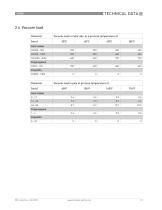
TECHNICAL DATA 22.4 Vacuum load Diameter
Open the catalog to page 17
2 TECHNICAL DATA2.5 Dimensions and weights Remote version Compact version with IMT33A Compact version with: IMT31A (0°) Compact version with: IMT31A (45°)
Open the catalog to page 18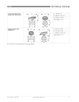
Compact stainless steel (10°) version with: IMT31A (10 ) Compact version with: (10°) IMT30A (10 ) 1 The value may vary depending on the used cable glands.
Open the catalog to page 19
2 TECHNICAL DATA • All data given in the following tables ane based on standand vensions of the flow sensor only. • Especially for smaller nominal sizes of the flow sensor, the signal converter can be bigger than the flow senson. • Note that for other pressure ratings than mentioned, the dimensions may be different. • For full information on signal converter dimensions see retevant documentation.
Open the catalog to page 20All Schneider Electric catalogs and technical brochures
 CFT34A
2 Pages
 IMT30A
2 Pages
 15607
156072 Pages
 IMV25
IMV252 Pages
 Evolis 24kV catalogue
80 Pages
 NEX 24 catalogue 2010
56 Pages
 ICatalogue CT VT
52 Pages
 Fuses catalogue 2012
24 Pages
 RM6 Catalogue
76 Pages
 Catalogue Human Machine Interfaces
150 Pages
 Osiswitch XCK_N catalogue
16 Pages
 Catalogue Osisense XG
26 Pages


- Power supply unit
- Flowmeter
- DC power supply
- AC/DC power supply
- Volume flow monitor
- Liquid flow monitor
- Ethernet switch
- Concentration analyzer
- Automation software solution
- Industrial network switch
- Schneider pressure transmitter
- Liquids analyzer
- Windows software
- Cloud-based software
- Analog pressure transmitter
- Managed switch
- Gas flow monitor
- Push-button switch
- Stainless steel flow monitor
- DIN rail mounted network switch