

V136

V136
Contact devices are designed for cases with a diameter starting at 100 mm and are available in single, double, and triple versions. They are installed below the ring dials, and the nominal values can be adjusted externally across the full scale. Contacts are categorized as follows: 1 = Closer, 2 = Opener, 3 = Change-over, with switching direction being clockwise. The document provides detailed switching schematics and circuit diagrams for common contact types.
- Low-action Contacts (S): Suitable for environments without high contact loads or vibrations. Not recommended for high-frequency switching, aggressive atmospheres, or liquid-filled instruments. Contact material is Ag80 Ni20, with a maximum breaking capacity of 10W DC or 18 VA AC. A contact protection relay (V 130) is recommended.
- Snap-action Contacts (M): Can be used in most conditions and are resistant to vibrations. They provide accelerated contact release through magnetic action. Contact material is Ag80 Ni20, with a maximum breaking capacity of 30W DC or 50 VA AC. A contact protection relay (V 130) is recommended.
- Electronic Contacts (E): Equipped with a 3-wire PNP proximity switch, suitable for direct control of electronic systems. Not approved for Ex-zones.
- Inductive Contacts (I): Feature non-touching proximity switches according to DIN 19234, suitable for industrial applications due to their precision and longevity. They are ideal for Ex-zones and can be used with isolating amplifiers for intrinsic safety.
The document details the switching functions for electromechanical and inductive limit signaling devices, including single, double, and triple contact configurations. Each configuration is explained with corresponding switching schematics and diagrams.
- Gauges with M-, E-, and I-contacts or microswitches can be filled with insulating oil.
- Diaphragm pressure gauges with ranges from 0-16 to 0-40 mbar cannot use M-contacts; only I-contacts are suitable.
Catalog excerpts

KONTAKTEINRICHTUNGEN CONTACT DEVICES Kontakteinrichtungen für Gehäuse ab 100 mm Durchmesser werden in Einfach-, Zweifach- und Dreifachausführung eingebaut. Die Montage erfolgt unter der Ringskala. Contact devices are used for cases starting at 100 mm diameter. The contacts are built in single-, double and triple versions. Installation will be below the ring dials. Die Sollwerte sind einzeln über den gesamten Skalenbereich von außen einstellbar. Jeder einzelne Kontakt wird wie folgt ausgeführt: The nominal values can be set from outside covering full scale. Each contact will be numbered as follows: Das Schaltverhalten gilt im Uhrzeigersinn. Switching direction is clockwise. Auf den folgenden Seiten sind die Schaltfunktionen der gängigsten 1-fach, 2-fach und 3-fach Kontakte mit Schaltschemata und Schaltbildern erklärt. On the following pages, the switching functions of the most common 1-way, 2-way and 3-way contacts are explained with switching schematics and circuit diagrams. Abbildung 1 – Schaltschema: Dünne Linie = Kontakt geöffnet, Stromkreis offen Dicke Linie = Kontakt geschlossen, Stromkreis geschlossen Illustration 1 – switching schematic Thin line = Contact open, circuit open Thick line = Contact closed, circuit closed Abbildung 2 – Schaltbild A Kontakt und Stromkreis geschlossen Illustration 2 – circuit diagramm A Contact and circuit closed Abbildugn 3 – Schaltbild B Kontakt und Stromkreis geöffnet Illustration 3 – circuit diagramm B Contact and circuit opened Irrtümer und technische Änderungen vorbehalten – Errors and technical modifications reser
Open the catalog to page 1
Zum Einbau einer Kontakteinrichtung wird eine Kabelanschlußdose V 119 und Bajonettring / Bajonettgehäuse oder Überring gemäß Typen V 125 / V126 oder V 127 benötigt. The installation of a contact device needs a junction box V 119 and bayonet lock bezel/ bayonet lock case or push-fit bezel acc. to types V 125/V 126 or V 127. Folgende Kontakteinrichtungen werden unterschieden: The different contact devices are: S. Schleichschaltung Schleichkontakte sind da zu verwenden, wo keine hohe Kontaktbelastung gefordert wird und keine Erschütterungen auftreten. Der Instrumentenzeiger führt den Schaltarm gegen...
Open the catalog to page 2
NG 100 + NG 160. Auf den sonst notwendigen Trennschaltverstärker kann verzichtet werden. E-Kontakte sind nicht für Ex-Schutz zugelassen. Schaltverhalten wie S- und M-Kontakte. I. Induktivschaltung I-Kontakte sind mit berührungslos arbeitenden elektrischen Wegaufnehmern nach DIN 19234 ausgerüstet. Sie eignen sich wegen der berührungslosen Schaltung, der Schaltgenauigkeit und der hohen Lebensdauer für jeden industriellen Einsatz. Das Ausgangssignal wird bestimmt durch die An- bzw. Abwesenheit einer vom Instrumentenzeiger bewegten Steuerfahne im Bereich des elektromagnetischen Feldes des Wegaufnehmers....
Open the catalog to page 3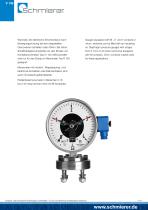
Wechsler, die elektrische Stromkreise je nach Bewegungsrichtung bei den eingestellten Grenzwerten schließen oder öffnen. Bei hoher Schalthäufigkeit empfehlen wir den Einsatz von Kontaktschutzrelais Type V 130. Mikroschalter sind nur für den Einbau in Manometer Typ R 100 geeignet. Gauges equipped with M-, E- and I-contacts or micro- switches can be filled with an insulating oil. Diaphragm pressure gauges with ranges from 0-16 to 0-40 mbar cannot be equipped with M-contacts. Only I-contacts maybe used for these applications. Manometer mit Induktiv-, Magnetspring- und Elektronik-Kontakten oder Mikroschaltern...
Open the catalog to page 4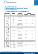
SCHALTFUNKTIONEN VON ELEKTROMECHANISCHEN GRENZSIGNALGEBERN SWITCHING FUNCTIONS OF ELECTROMECHANICAL LIMIT SIGNALING DEVICESS Schaltschema Schaltfunktion (Zeigerbewegung im Uhrzeigersinn) Kontakttyp Magnetspringkontakt Kontakt schließt Kontakt öffnet Kontakt schaltet um: ein Kontakt öffnet und ein Kontakt schließt 1. Kontakt schließt 2. Kontakt schließt 1. Kontakt schließt 2. Kontakt öffnet 1. Kontakt öffnet 2. Kontakt schließt 1. Kontakt öffnet 2. Kontakt öffnet 1. Kontakt öffnet 2. Kontakt schließt 3. Kontatk öffnet 1. Kontakt schließt 2. Kontakt öffnet 3. Kontakt schließt Irrtümer und technische...
Open the catalog to page 5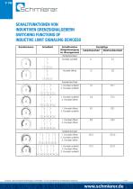
SCHALTFUNKTIONEN VON INDUKTIVEN GRENZSIGNALGEBERN SWITCHING FUNCTIONS OF INDUCTIVE LIMIT SIGNALING DEVICESS Schaltschema Schaltfunktion (Zeigerbewegung im Uhrzeigersinn) Kontakttyp Induktivkontakt Kontakt schließt Kontakt öffnet 1. Kontakt schließt 2. Kontakt schließt 1. Kontakt schließt 2. Kontakt öffnet 1. Kontakt öffnet 2. Kontakt schließt 1. Kontakt öffnet 2. Kontakt öffnet 1. Kontakt öffnet 2. Kontakt schließt 3. Kontatk öffnet 1. Kontakt schließt 2. Kontakt öffnet 3. Kontakt schließt Irrtümer und technische Änderungen vorbehalten – Errors and technical modifications reserved
Open the catalog to page 6All Schmierer GmbH catalogs and technical brochures
 Schmierer GmbH Brochure
14 Pages
 PKU100
2 Pages
 PGU250
2 Pages
 PGU100
2 Pages
 PAKU100
2 Pages
 PAGU160
2 Pages
 BU160
BU1602 Pages
 BU100
BU1002 Pages
 DKU100
2 Pages
 R1000
R10002 Pages
 FU250
FU2502 Pages
 F160
F1602 Pages
 GFU160
2 Pages
 GU250
GU2502 Pages
 GU160
GU1602 Pages
 GU100
GU1002 Pages
 M200
M2002 Pages
 RU250
RU2502 Pages
 R400
R4002 Pages
 R630
R6302 Pages
 RU40
RU402 Pages
 RU50
RU502 Pages
 RU63
RU632 Pages
 R100
R1002 Pages
 RU100
RU1002 Pages
 R160
R1602 Pages
 RU160
RU1602 Pages
 R40 R50 R63
2 Pages
- Pressure transmitter
- Analog pressure gauge
- Industrial thermometer
- Relative pressure transmitter
- Stainless steel pressure gauge
- Digital pressure transmitter
- Dial pressure gauge
- Threaded pressure gauge
- Gas pressure transmitter
- Liquid pressure transmitter
- Gas pressure gauge
- Process pressure transmitter
- Waterproof thermometer
- Stainless steel thermometer
- Bourdon tube pressure gauge
- Differential pressure transmitter
- Analog thermometer
- Liquid pressure gauge
- Differential pressure gauge