- Catalogs
- Schildknecht AG
- Antenna 101
Antenna 101
1 /37Pages

Antenna 101
1 /37Pages
Catalog excerpts

SCHILDKNECHT SMART DATA COMMUNICATION
Open the catalog to page 1
2.2 The radiation characteristics of an antenna 05 3.1 DATAEAGLE device connector 10 4. Guidelines for antenna assembly 15 4.5 Separation and free radiation 19 4.10 Consider the protection class (IP) 22 5.1 Two fixed objects or with linear movement 24 5.2 Two turning objects or mobile applications 24 5.3 One fixed and one turning object 25 6.5 Omnidirectional antennas for cellular radio 31-32 7. Closing remarks and contact info 36
Open the catalog to page 2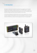
1. Introduction What does an antenna do? It transmits and receives electro magnetic waves. To transmit, the antenna converts electric energy, for instance from a DATAEAGLE device, into electro magnetic waves. To receive, it works the other way round, converting electro magnetic waves into electric energy. You need to choose the right antenna and to mount it correctly to ensure the best transmission path and thus optimal conditions for data transfer. In this Antenna 101 guide you can find all relevant technical terms explained. Also, we describe the specific antennas suited for different kinds...
Open the catalog to page 3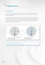
2. Technical terms 2.1 Antenna gain The gain of an antenna indicates the increase of its transmission energy. Gain is a result of transmission energy focused through the antenna in horizontal and/or vertical direction (see 2.2 opening angle). A ball emitter emitting transmission energy uniformly in all directions has no antenna gain (0 dBi or 0 dBd). The ball emitter is a theoretical concept used for calculating antenna gain. Omnidirectional antennas radiate transmission energy horizontally in a 360° radius, while less than 360° on a vertical axis. This means for instance that the antenna item...
Open the catalog to page 4
2. Technical terms 2.2 The radiation characteristics of an antenna The radiation characteristics of an antenna, also called opening angle or beam width, is a graphical representation of the directivity of an antenna. The opening angle refers to the area in which you have at least half of maximum radiated power available. Vertical opening angle Horizontal opening angle 360° The narrower the opening angle, the longer the reach. The larger the opening angle, the shorter the reach.
Open the catalog to page 5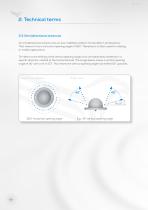
2. Technical terms 2.3 Omnidirectional antennas An omnidirectional antenna has an even radiation pattern horizontally in all directions. That means it has a horizontal opening angle of 360°. Therefore it is often used for rotating or mobile applications. Tilt refers to the shifting of the vertical opening angle of an omnidirectional antenna in a specific direction, related to the horizontal level. The image below shows a vertical opening angle of 40° with a tilt of 20°. This means the vertical opening angle has shifted 20° upwards. View from above Side view 360° horizontal opening angle
Open the catalog to page 6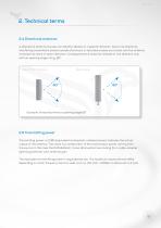
2. Technical terms 2.4 Directional antennas A directional antenna focuses its radiation density in a specific direction. Due to its directivity, interfering transmitters placed outside of primary or secondary lobes are muted, and the antenna increases its reach in beam direction. Consequently the antenna radiates in one direction only, with an opening angle of e.g. 80°. View from above Side view Example: horizontal/vertical opening angle 80° 2.5 Transmitting power Transmitting power, or EIRP (equivalent isotropically radiated power) indicates the actual output of the antenna. This value is a...
Open the catalog to page 7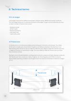
2. Technical terms 2.6 Link budget Link budget measures the difference between radiation power (EIRP) and receiver sensitivity. The link budget allows you to estimate the reach of the signal. To get a correct estimate you have to take a number of factors into account: - Radiation power - Antenna gain - Receiver sensitivity - Free space loss - Cable attenuation 2.7 Fresnel zone A Fresnel zone is a 3-dimensional ellipse drawn between transmitter and receiver. The radius of this zone is made up by transmission frequency and distance between the antennas. In an ideal setting there should not be any...
Open the catalog to page 8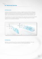
2. Technical terms 2.8 Polarization Polarization indicates the direction of vibrations created by the electric field. You distinguish between horizontal and vertical linear polarization (VP), and right hand circular polarization (RHCP). The transmitting and the receiving antenna should have identical polarization. If you deploy unequally polarized antennas you can experience loss or no radio connection at all. We use antennas with vertical linear polarization (VP) or right hand circular polarization (RHCP). An RHCP antenna is suitable for directional antennas with sight connection. For all other...
Open the catalog to page 9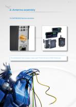
3. Antenna assembly 3.1 DATAEAGLE device connector The DATAEAGLE lines Compact, Classic and X-Treme all have an SMA-female port.
Open the catalog to page 10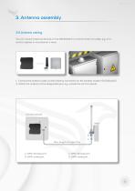
3. Antenna assembly 3.2 Antenna cabling You can mount antennas directly on the DATAEAGLE or connect them via cable, e.g. on a control cabinet or mounted on a mast. 1. Connect the antenna cable via the antenna connection on the wireless modem (DATAEAGLE) 2. Attach the antenna at the designated spot, e.g. outside the control cabinet Mast B D Max. length of cable 10m A: SMA-female port B: SMA-male port C: SMA-female port D: SMA-male port
Open the catalog to page 11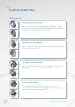
3. Antenna assembly 3.3 Connections SMA-male and SMA-female SMA plug connectors are suited for frequency bands from 1 GHz to 18 or 26,5 GHz, dependent on model. SMA plug connectors are rather small, but yet very robust due to their screw lock. FME-male and FME-female These miniature plug connectors have an electrical impedance of 50Ω for frequencies up to 2 GHz. TNC-male and TNC-female These are coaxial plug connectors for high frequencies up to approx. 11 GHz. They are connected to each other by screw threads. N-male and N-female These coaxial plug connectors with screw lock are suited for frequencies...
Open the catalog to page 12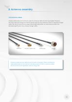
3. Antenna assembly 3.4 Antenna cables To keep attenuation at a minimum, keep the antenna cable as short as possible. However, the most important thing is to find the perfect spot for your antenna, even if it requires a longer cable. We recommend that you keep cable length below 10m, as transmission power will decrease significantly if you choose a longer cable. Antenna cables are very delicate and should not be bent. When installing the cable please observe its maximum bending radius of 30mm. Antenna cables should only be hand-tightened, without using tools.
Open the catalog to page 13All Schildknecht AG catalogs and technical brochures
 Wireless 101 Whitepaper
5 Pages
 The World is Wireless
6 Pages
 Sensor 2plc
2 Pages
 DATAEAGLE catalog 2.2
53 Pages
 catalogue of all products
104 Pages


- Data logger
- Temperature datalogger
- Communication gateway
- Industrial gateway
- Fieldbus gateway
- Ethernet gateway
- Serial gateway
- Wireless gateway
- DIN rail gateway
- IoT gateway
- RS-485 gateway
- RS-232 gateway
- Compact datalogger
- Modbus gateway
- Condition monitoring module
- Digital datalogger
- Compact gateway
- IP67 antenna
- Remote monitoring module