- Catalogs
- Schick Industrie
- Schick IQ1
Schick IQ1
1 /20Pages
Schick IQ1
1 /20Pages
Catalog excerpts
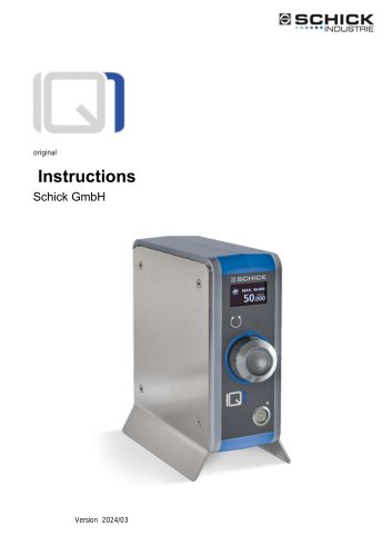
SCHICK ■--■INDUSTRIE Instructions Schick GmbH
Open the catalog to page 1
^Ve are pleased that you have decided in favor of a technically high-quality device from SCHICK and wish you every success with your new IQ1 control device and that you enjoy working with it. Ve have compiled these operating instructions to familiarize you with your new device and to provide you with the necessary information for operation and m ai ntenan ce. Type: I ndustrial control unit for handpieces and spindles
Open the catalog to page 2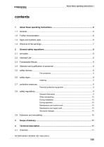
About these operating instructions 1
Open the catalog to page 3
About these operating instructions 1
Open the catalog to page 5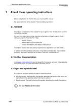
1 About these operating instructions About these operating instructions Before using the IQ1 for the first time, you must read this manual. Pay special attention to the chapter 2"General safety regulations 1.1 General This manual is intended to make it easier for you to get to know the IQ1 and to use it for its intended purposes. The operating instructions contain important information on how to operate the IQ1 safely and properly. Your attention helps: Reduce repair costs and downtime increase the reliability and lifespan of the product This manual must be read and used by anyone who is assigned...
Open the catalog to page 6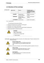
About these operating instructions 1 warning levels signal word The warnings are structured as follows, Pictogra m with signal word according to warning level Description of the hazard (hazard type) Description of the consequences of the hazard (hazard consequences) M easures (activities) to prevent the hazard DANGER!Type of hazard (text) Consequences of danger > S ecurity (text) warning sign Special safety instructions are given at the relevant places. They are marked with the following symbols. General danger spot This sign is placed in front of activities where there is a risk of personal...
Open the catalog to page 7
2 General safety regulations General safety regulations 2.1 principles Use only at the maximum speeds specified by the tool manufacturer. Use only tools specified by the manufacturer/dealer for the application and performance specifications of the IQ1. Area of application: industry, trade Personnel qualification: Apprentices and interns only after instruction by an experienced operator It is operated manually: either with a rotary knob or a foot pedal. 2.2 Intended Use The IQ1 systems are intended exclusively for universal use in commercial operations for processing solid materials. Only tools...
Open the catalog to page 8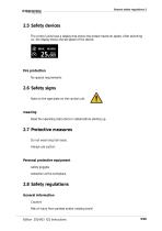
General safety regulations 2 2.5 Safety devices The control units have a display that shows the preset maximum speed. After switching on, the display shows the set speed of the device. Fire protection No special requirements 2.6 Safety signs Note on the type plate on the control unit. meaning Read the operating instructions in detail before starting up. 2.7 Protective measures Do not wear long hair loose. Always use suction. Personal protective equipment safety goggles extraction at the workplace. 2.8 Safety regulations General information Caution! Risk of injury from pointed and/or rotating...
Open the catalog to page 9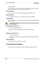
2 General safety regulations Wear safety glasses. The handpiece can become very hot under high and prolonged loads. Reduce the contact pressure or interrupt work until the handpiece has cooled down. While transporting Transport or dispatch only in the original packaging or suitable shipping carton. During installation Access to the power supply must not be made more difficult by the installation. During operation Operation and operation only with a sufficiently designed extraction system and protective clothing provided. In anti-clockwise rotation mode, the collet chuck may come loose when using...
Open the catalog to page 10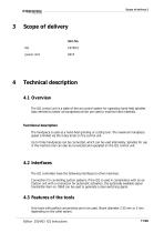
Scope of delivery Item No. power cord Technical description 4.1 Overview The IQ1 control unit is a state-of-the-art control system for operating hand-held spindles (also referred to below as handpieces) which are used to machine hard materials. Functional description The handpiece is used as a hand-held grinding or cutting tool. The maximum handpiece speed is limited via the rotary knob on the control unit. Up to three handpieces can be connected, which can be used alternately. Spindles for use in the machine tool can also be connected and operated on the IQ1 control unit. 4.2 Interfaces The...
Open the catalog to page 11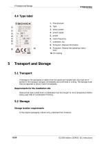
Irtrfor -4fr Hfit 950CVO mwm *,chrk ikrititl rlr 8. P ictogra m : Disposal information 9. P ictogra m : Observe the operating instructions serial number power supply 5 Transport and Storage5.1 Transport If damage to the packaging is visible when the goods are handed over, this must be reported to the transport company immediately and confirmed in writing. The damage must then be reported to Schick Gm bH im mediately. Requirements for the installation site Devices that have cooled down considerably must be brought to room temperature before being used. Risk of condensation forming. Storage location...
Open the catalog to page 12
pull out the mains plug 6.2 InstallationEstablish supply Mill (Handpiece 3) foot pedal (optional) Signal cable for suction > C o nnect existing ha nd pieces/spindles to socket Ml > O ptional, Connect a foot pedal to the foot pedal jack ^ Plug the mains adapter plug into the power supply socket on the control unit.
Open the catalog to page 13
Functions and operation 7.1 IQ1 Controller On/Off Switching on/off takes place via the main switch on the front of the control unit. Readiness indication via display or LED on the main switch. The IQ1 control unit may only be switched off using the main switch when the handpiece is stationary. 7.2 Operating concept and OLED display After switching on, the OLED display of the IQ1 control unit provides information about all operating states of the device. The following parameters are displayed in detail: - operational readiness: Display shows the selected/connected handpiece, the prese- Operating...
Open the catalog to page 14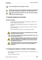
The inverted display shows the handpiece is running! With dynamic control with dyn. after starting the handpiece, the previously set maximum speed is displayed in the display line "LIM." (abbreviation LIMIT). When using the optional pedal switch item no. 6370/2 the symbol is displayed only when the pedal is pressed. 7.3 Operate handpiece and controller Starting the handpiece Variable speed control via optional dynamic foot pedal item no. 9440 up to the maximum speed set via the rotary knob. Static handpiece start by pressing the rotary knob tary knob. Static handpiece start via the optional foot...
Open the catalog to page 15All Schick Industrie catalogs and technical brochures
 MT A
MT A23 Pages
 Schick IQ3
21 Pages
Archived catalogs
 Precision technology
12 Pages
- LED lighting
- Dust collector
- Control pedal
- Single pedal pedal
- Electronic pedal
- Filter dust collector
- Lamp
- Motorized spindle
- Deburring tool
- Suction unit
- Compact dust collector
- Milling spindle
- Digital control unit
- Machining spindle
- High-efficiency lighting
- Energy saving lighting
- Automatic control unit
- Metal deburring tool
- Industrial suction unit
- Grinding spindle