
- Catalogs
- Schaeffler Technologies AG & Co. KG
- Needle roller and cage assemblies for crank pins and piston pins (TPI 94)


- Company
- Products
- Catalogs
- News & Trends
- Exhibitions
Needle roller and cage assemblies for crank pins and piston pins (TPI 94)

Needle roller and cage assemblies for crank pins and piston pins (TPI 94)
Needle roller and cage assemblies are essential components in the crank mechanisms of 2 and 4 stroke engines and compressors. They support crank and piston pins, are designed for high speeds, and require minimal radial space.
Features
These assemblies ensure high runout accuracy, influenced by the raceway's geometrical precision. The radial internal clearance is determined by needle roller type and shaft/housing tolerances. Raceways must be hardened, ground, and honed for optimal performance.
Design and Safety Guidelines
Guidance of the Connecting Rod: Differentiates between crank end and piston end guidance, with specific requirements for each.
Design of Adjacent Parts: Bores and pins should be treated as rolling bearing raceways with specific roughness and hardness, including lubrication pockets and slots.
Preferred Enveloping Circle Diameter
Dimensions are based on cylinder capacity, with tables providing preferred diameters for 2 stroke engines and technical data for 4 stroke engines.
Accuracy
Specifies geometrical tolerances for raceways and permissible deviations for crank and piston pin bearing arrangements.
Radial Internal Clearance
Determined by needle roller type, with specific minimum values for crank and piston pin arrangements.
Sort Plans
Details conditions for bearing arrangements, including bore and pin tolerances, needle roller types, and radial internal clearance.
Special Designs
Includes split, copper plated, and silver plated cages for high-performance machines.
Ordering Example
Provides an example of ordering designation for a needle roller and cage assembly.
Dimension Tables
Includes dimensions, mass, and load ratings for assemblies.
Appendix
Includes calculation of rolling bearings in crank machines and datasheets for further technical details.
This document outlines the calculation method for determining the basic rating life (L10) of bearings in crank mechanisms, based on DIN ISO 281, considering internal load distribution and dynamic loading.
Calculation Method
The method extends standard calculations by including internal load distribution effects, assuming identical load and geometry for power train units, and excluding lubrication influences.
Adjusted Reference Rating Life
The adjusted reference rating life (Lnmr) is calculated per DIN ISO 281, incorporating material fatigue limit load, lubrication conditions, and contamination type and size.
Fatigue Theory
Based on Lundberg and Palmgren’s fatigue theory, with an expanded model by Ioannides and Harris for better performance description.
Data Collection
Data for calculations is collected using datasheets, including engine data and load cases.
Load Cases and Static Forces
Defined by ignition pressure, time proportion, and speed, detailing static forces on the crankshaft.
Functional Diagrams
Includes diagrams illustrating pressure over speed and load over time scenarios.
Contact Information
Schaeffler Technologies provides contact details for further inquiries and technical support.
Catalog excerpts

Needle roller and cage assemblies for crank pins and piston pins
Open the catalog to page 1
Needle roller and cage assemblies for crank pins and piston pins Product overview Special designs Ordering example and ordering designation Features Design and safety guidelines Dimension tables Schaeffler Technologies
Open the catalog to page 3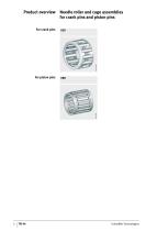
Product overview Needle roller and cage assemblies for crank pins and piston pins KZK Schaeffler Technologies
Open the catalog to page 4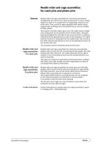
Needle roller and cage assemblies for crank pins and piston pins Features Needle roller and cage assemblies for connecting rod bearing arrangements are used in the crank mechanisms of 2 and 4 stroke engines as well as in compressors for supporting crank pins and piston pins. They consist of cages equipped with needle rollers, support high centrifugal and acceleration forces and are suitable for high speeds. They require very little radial space since the radial section height only corresponds to the diameter of the needle rollers. They give bearing arrangements with high runout accuracy which...
Open the catalog to page 5
Needle roller and cage assemblies for crank pins and piston pins Figure 1 Crank end guidance – lateral guidance of the connecting rod Piston end guidance Figure 2 Piston end guidance – lateral guidance of the connecting rod The connecting rod and needle roller and cage assembly KZK are guided axially between the crank webs, Figure 1. The connecting rod eye at the crank end must have lubrication pockets and slots to allow the supply of lubricant. The KBK is guided axially between the piston boss abutment surfaces. Free lateral movement of the connecting rod between the piston bosses. Depending...
Open the catalog to page 6
Design of adjacent parts Proven materials for adjacent parts The bores and pins for the needle roller and cage assemblies must be produced as rolling bearing raceways. A roughness Rz1 (Ra0,2) must be ensured. The rolling bearing raceways, thrust surfaces and thrust washers must be as follows: ■ case hardened to at least 0,5 mm deep; a surface hardness of at least 700 HV must be ensured. ■ The lateral thrust surfaces should be precision machined (Ra2 recommended) and wear resistant; thrust washers should be fitted if necessary. For lubrication of the needle roller and cage assemblies, holes or...
Open the catalog to page 7
Needle roller and cage assemblies for crank pins and piston pins Accuracy Permissible geometrical tolerances for crank pin bearing arrangements The geometrical tolerances of the raceways must be in accordance with the tables and Figure 3 and Figure 4. Nominal dimension Figure 3 Geometrical tolerances for crank pin bearing arrangements Permissible geometrical tolerances for piston pin bearing arrangements Nominal dimension Figure 4 Geometrical tolerances for piston pin bearing arrangements Schaeffler Technologies
Open the catalog to page 8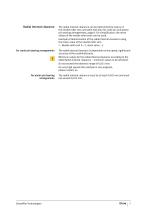
Radial internal clearance For crank pin bearing arrangements For piston pin bearing arrangements Schaeffler Technologies The radial internal clearance can be determined by means of the needle roller sort, see table Sort plan for crank pin and piston pin bearing arrangements, page 8. For simplification, the mean values of the needle roller sorts can be used. Example of determination of the radial internal clearance using the mean value of the needle roller sort: ■ Needle roller sort 0 –2, mean value –1. The radial internal clearance is dependent on the speed, rigidity and accuracy of the crankshaft...
Open the catalog to page 9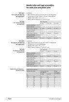
Needle roller and cage assemblies for crank pins and piston pins Sort plan for crank pin bearing arrangements Sort plan for crank pin bearing arrangements Conditions: ■ Bore tolerance G6 for 18 mm to 30 mm in three groups ■ Pin tolerance h5 for 14 mm to 18 mm in three groups ■ Needle roller sort 0 –2 to –5 –7 ■ Radial internal clearance 17 m to 30 m. Bore deviations +7 +11 Crank pin deviation Needle roller sort Needle roller sort Radial internal clearance Needle roller sort Radial internal clearance Sort plan for piston pin bearing arrangements Radial internal clearance Sort plan for piston...
Open the catalog to page 10
Special designs Ordering example and ordering designation Schaeffler Technologies Needle roller and cage assemblies KZK are available by agreement in the following designs: ■ split cage, suffix D ■ copper plated cage, suffix CU ■ silver plated cage, suffix AG ■ for high performance machines. Needle roller and cage assembly KZK for: ■ crank pin 16 mm ■ connecting rod bore 22 mm ■ width 12 mm ■ needle roller sorts (sort pair coded blue) –2 –4 and –3 –5 ■ copper plated cage. Ordering designation: ■ KZK16ϫ22ϫ12 SORT–2–4/–3–5–CU
Open the catalog to page 11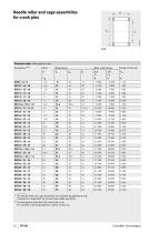
Needle roller and cage assemblies for crank pins Dimension table · Dimensions in mm Designation1) 2) Basic load ratings stat. C0r Fatigue limit load The needle roller and cage assemblies are available by agreement only. Production is dependent on economically viable quantities. The designation describes the dimensions only. For a precise ordering designation, please contact us. Schaeffler Technologies
Open the catalog to page 12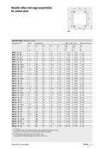
Needle roller and cage assemblies for piston pins Dimension table · Dimensions in mm Designation1)2) Basic load ratings Fatigue limit load The needle roller and cage assemblies are available by agreement only. Production is dependent on economically viable quantities. The designation describes the dimensions only. For a precise ordering designation, please contact us. Schaeffler Technologies
Open the catalog to page 13
Needle roller and cage assemblies for crank pins and piston pins Appendix Calculation of rolling bearings in crank machines Our calculation method can be used to calculate the basic rating life L10 of the bearings (needle roller and cage assemblies for crank pins and piston pins, main bearings) in the crank mechanism of internal combustion engines on the basis of DIN ISO 281. In comparison with the standardised calculation to DIN ISO 281, it additionally takes into consideration the influence of internal load distribution in the bearing on the rating life. The calculation method takes account...
Open the catalog to page 14
Datasheet · Needle roller and cage assemblies for crank pins and piston pins Customer data Enquiry data Proposal deadline Delivery date Annual volume Required rating life Engine data Engine type Cylinder bore Engine power Mass of longitudinally guided parts Mass of rotating parts Design data for connecting rod Connecting rod length Centre of gravity of connecting rod LS1) _________________ mm Design data for crankshaft main bearing arrangement2) Crank-conrod offset distance Position of brg. C xC1) _________________ mm Oscillating mass compensation Bearings for calculation Bearing A1) See functional...
Open the catalog to page 15All Schaeffler Technologies AG & Co. KG catalogs and technical brochures
 ProLink CMS
2 Pages
 Split plummer block housings SNV
84 Pages
 Always Following the Sun
12 Pages
 Active Magnetic Bearing
4 Pages
 RDDM Rotary Direct Drive Motors
106 Pages
 FAG RS ? Robust and Fast
6 Pages
 FAG Alignment Tools
36 Pages
 Split Plummer Block Housings SNS
68 Pages
 FAG SmartCheck
2 Pages
 Customized Hubridization
20 Pages
 Crossed roller bearings
67 Pages
 Bearings for screw drives
106 Pages
 Sealing rings
35 Pages
 Sealed Spherical Roller Bearings
24 Pages
 Spherical Roller Bearings E1
40 Pages
 Tapered Roller Bearings E1
4 Pages
 Single Row Ball Roller Bearings
18 Pages
 Super Precision Bearings
243 Pages
 Slewing rings
108 Pages


Archived catalogs
 Triondur
2 Pages
 FAG E1 Spherical Roller Bearings
28 Pages


- Flowmeter
- Liquid flow monitor
- Actuator
- Linear actuator
- Positioning table
- Measuring machine
- Schaeffler steel bearing
- Waterproof flow meter
- Translation stage
- Synthetic lubricant
- Servo-motor
- Nut
- Schaeffler ball bearing
- Schaeffler radial bearing
- Metal nut
- Compact actuator
- Compact flow monitor
- Screw actuator
- High-performance servo motor