- Catalogs
- Schaeffler Technologies AG & Co. KG
- Miniature linear guidance set with cylindrical roller flat cages (MAI 79)
Miniature linear guidance set with cylindrical roller flat cages (MAI 79)

Miniature linear guidance set with cylindrical roller flat cages (MAI 79)
The miniature linear guidance set is engineered for limited stroke lengths, offering high load capacity, rigidity, and running accuracy. It supports loads from all directions except the motion direction and can be configured in O or X arrangements. It is suitable for temperatures up to +120°C and can be lubricated with oil or grease.
Load Carrying Capacity and Rating Life
The load capacity is determined by basic dynamic and static load ratings. Adjustments are needed for temperatures above +120°C. The basic rating life is calculated using specific formulas, considering stroke length and load factors.
Static Load Safety Factor
This factor ensures the bearing's accuracy and smooth operation without permanent deformation, requiring a minimum of 3 for high accuracy demands.
Preload
Preloading enhances rigidity and accuracy but impacts displacement resistance and operating life. It is set based on the guideways' fixing method.
Location of Guideways
Guideways feature standard counterbored fixing holes and can be mounted using insert nuts ESM. Proper deburring of adjacent construction holes is crucial to prevent defects.
Insert Nuts ESM
Used for guideway location, these must be fixed with adhesive. Components should be cleaned and dried before application.
Accuracy
Defined accuracy classes specify tolerances for parallelism and length, ensuring the guideways maintain proper function.
Accessories and Ordering
Accessories like insert nuts ESM must be ordered separately, with designations varying based on guideway lengths and configurations.
Catalog excerpts

with cylindrical roller flat cages >
Open the catalog to page 1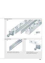
Miniature linear guidance set RWS > 172 746 Cylindrical roller flat cage > cage strip made from corrosion-resistant steel > end pieces made from steel > cylindrical rollers in accordance with DIN 5402-1 > end pieces for guideways of unequal length; fixing by hexagonal socket head screws >
Open the catalog to page 3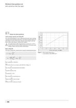
1,20,80,60,40,20 Design and safety guidelinesLoad carrying capacity and rating life > 1,0 The size of the guidance unit is determined by the load carrying capacity of the individual elements. The load carrying capacity is described in terms of the basic dynamic load rating C and the basic static load rating C > (dimension tables). For applications with temperatures in excess of +120 C, factors must be used to reflect reductions in the basic load ratings. Please ask for further information. > KHV k Basic rating life > 00,20,40,60,81,21,0 The basic rating life is determined using the following...
Open the catalog to page 4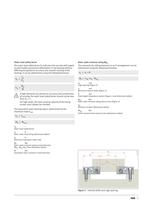
Static load safety factor Basic static moment rating M > 0x The static load safety factor S > indicates the security with regard to permissible permanent deformation in the bearing without affecting the guidance accuracy and smooth running of the bearing. It can be determined using the following formula:If high demands are placed on accuracy and smoothness of running, the static load safety factor should not be less than S The moments for rolling elements in an O arrangement can be determined using the following formulae: a > k = a > i + B C S ------= > > M = k +a ⋅ W P > > M k M 0x a k mmCage...
Open the catalog to page 5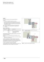
Preload The guidance systems must be preloaded (Table 1). Preload: ■ increases the rigidity and guidance accuracy ■ reduces the high loads on the rolling elements at the ends ofthe cage under moment load (about the Z and Y axes). Thistherefore increases the moment load carrying capacity ofthe guidance system.However, preload also influences the displacement resistance and the operating life of cage guidance systems. The guideways can be fixed through the adjacent construction or through the guideways. Depending on the fixing method used, the preload is set as follows: > d Table 1 Preload class...
Open the catalog to page 6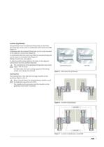
Location of guideways The guideways have counterbored fixing holes as standard. Thishole type can be used in combination with insert nuts ESM (Figure 5).Guideways with the standard fixing hole can be screw mounted to the adjacent construction (Figure 6).In combination with the insert nuts ESM, the standard fixing hole can be used as a threaded hole (Figure 7). Fitting of insert nuts: see page 8.In order to avoid location defects, the holes in the adjacent construction must be carefully deburred.The counterbores of the guideway fixing holes have sharp edges. Risk of injury!For high loads, the...
Open the catalog to page 7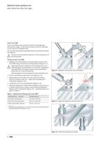
Insert nuts ESM Insert nuts ESM are accessories for location of guideways ( > 156 227 Accessories , page 13). By means of these nuts, this hole type can be used as a threaded hole. The nuts must be ordered separately and are included loose with the delivery.The nuts must be fixed by adhesive in the counterbores of the fixing holes. Fitting of insert nuts ESM ■ Degrease the counterbores in the guideway and the insert nuts ESM using conventional cleaning agents (Figure 8, ). Legal specifications relating to the handling and use of cleaning agents (manufacturers instructions, regulations covering...
Open the catalog to page 8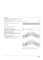
Hole patterns The hole pattern is symmetrical: In this case, a > L = a > R (Figure 11).For guideways with a symmetrical hole pattern: a == 12 > a L j L RL = aa L a > R --- L nj ֢˅() > L a L , a R mmDistance between start or end of guideway and nearest holeLmmGuideway lengthnMaximum number of pitches between holesj L mmHole spacing ( dimension tables ). 156 200 Rolling elements in O and X arrangements Figure 11 ַ Symmetrical hole pattern The rolling elements can be changed to an O or X arrangement by changing over the cages (Figure 12). > 156 201 Delivered condition/initial operation > O arrangement...
Open the catalog to page 9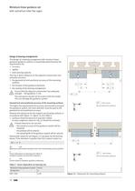
Design of bearing arrangements The design of a bearing arrangement with minature linear guidance guidance systems is essentially determined by the requirements for: ■ accuracy ■ rigidity > H ■ load carrying capacity.This has a direct influence on the adjacent construction and primarily concerns: ■ the geometrical and positional accuracy of the mounting surfaces > AAA ■ the location of the guidance elements > ttttt tt ■ the sealing of the bearing arrangement. Ensure that the adjacent construction has adequate strength VDI guideline 2230.The end pieces should not be used to limit the stroke. Thiscan...
Open the catalog to page 10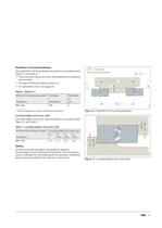
Parallelism of mounted guideways The parallelism t of the guideways should be in accordance with Figure 14 and Table 4: > t Not convex(for all machined surfaces) tC ■ If the maximum values are used, the displacement resistance may increase ■ For larger tolerances, please contact us. > b C ■ Table 4 Value for t For calculation of H, see page 10. > H Miniature linear guidance system Guideway Parallelism t 1) Designation Designation mRWS 1808RW5 Figure 14 Parallelism of mounted guideways > t 152 151 1) Value for guidance system set free from clearance. Locating heights and corner radii Locating...
Open the catalog to page 11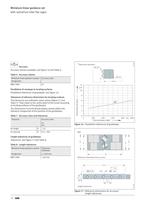
Permissible deviation 1000 Total guideway length Measured deviation > Reference dimensions for accuracy Length tolerances LC > 1 / n j > L 0,25 0,4 a j > L 152 168
Open the catalog to page 12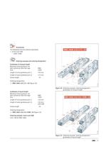
Accessories The following must be ordered separately: ■ Insert nuts ESMsuffix +ESM. Ordering example and ordering designationGuideways of unequal length 150 mmLength of outer guideway pair 175 mmStroke length20 Miniature linear guidance setwith cylindrical roller flat cageRWSSize1808Length of inner guideway pair Ordering designation:1 RWS 1808 150/175 20 (Figure 18). > 172 764 Figure 18 ַ Ordering example, ordering designation guideways of unequal length Guideways of equal length 150 mmLength of outer guideway pair 150 mmwith ESMStroke length20 Ordering designation:1 RWS 1808 150/150 +ESM 20...
Open the catalog to page 13All Schaeffler Technologies AG & Co. KG catalogs and technical brochures
 ProLink CMS
2 Pages
 Split plummer block housings SNV
84 Pages
 Always Following the Sun
12 Pages
 Active Magnetic Bearing
4 Pages
 RDDM Rotary Direct Drive Motors
106 Pages
 FAG RS ? Robust and Fast
6 Pages
 FAG Alignment Tools
36 Pages
 Split Plummer Block Housings SNS
68 Pages
 FAG SmartCheck
2 Pages
 Customized Hubridization
20 Pages
 Crossed roller bearings
67 Pages
 Bearings for screw drives
106 Pages
 Sealing rings
35 Pages
 Sealed Spherical Roller Bearings
24 Pages
 Spherical Roller Bearings E1
40 Pages
 Tapered Roller Bearings E1
4 Pages
 Single Row Ball Roller Bearings
18 Pages
 Super Precision Bearings
243 Pages
 Slewing rings
108 Pages


Archived catalogs
 Triondur
2 Pages
 FAG E1 Spherical Roller Bearings
28 Pages


- Flowmeter
- Liquid flow monitor
- Actuator
- Linear actuator
- Positioning table
- Measuring machine
- Schaeffler steel bearing
- Waterproof flow meter
- Synthetic lubricant
- Translation stage
- Servo-motor
- Schaeffler ball bearing
- Schaeffler radial bearing
- Metal nut
- Compact actuator
- Compact flow monitor
- Screw actuator
- High-performance servo motor