
- Catalogs
- SCANLAB GmbH
- SCANalign Vision System


SCANalign Vision System

SCANalign Vision System
SCANalign is a comprehensive vision solution designed for laser scan systems, enhancing them with precise calibration, automatic process alignment, and visual quality control. It integrates seamlessly with SCANLAB's scan heads and laserDESK software, providing a user-friendly interface for system calibration and vision job execution.
- Fast, high-precision calibration of the laser system.
- Ultra-accurate position measurement within the scan field.
- Automatic alignment of laser processes to workpiece positions.
- Capture and correction of images before and after laser processing.
- Integration with laserDESK software for enhanced functionality.
- Software package, camera, illumination, and calibration plate.
- Compatible with SCANLAB's scan heads, camera adapters, and RTC5 control boards.
- Adaptable to specific laser application requirements.
Two configurations are available: side-mounted and coaxial camera setups. Both allow GUI-based calibration and control, facilitating adaptation to specific system designs. The system includes interfaces and cabling for communication between components.
Camera calibration is performed for each mirror position, ensuring precise laser marking. A calibration plate is used for absolute calibration of field coordinates, optimizing laser processing across multiple systems.
The Development Interface allows for scan system calibration and vision job definition, while the Production Interface enables monitoring of intermediate results. Both interfaces support local and remote operation.
SCANalign integrates with laserDESK, allowing predefined vision jobs to be incorporated into laserDESK jobs. The Vision Engine executes these jobs and returns results, facilitating manual alignment and process structuring.
- Desktop PC with PCI or PCIe bus and RTC5 control board.
- 32-bit or 64-bit Windows operating system.
- USB ports for SCANalign/laserDESK dongles.
- PC internal power supply with specific voltage and current requirements.
- Training on a demo system at SCANLAB.
- Development of customer-specific vision jobs.
- Support on illumination and installation.
Packages include software, IO board, cabling, camera, illumination, and optional components like calibration plates and laserDESK software. Components must be selected based on specific laser application requirements.
Details of coaxial and side-mounted camera setups, including specifications for scan head aperture, control board, laser wavelength, camera resolution, and calibration accuracy.
Catalog excerpts

self-aligned laser processing SCANalign is a complete, easy-to-use vision solution specifically developed for laser scan systems. SCANalign extends your scan system with highly precise calibration of the whole working field, automatic process alignment and visual quality control of laser processing results. SCANalign's key components are a software package, a camera, suitable illumination and a high-precision calibration plate. SCANalign's software enables: • All SCANalign packages are adaptable to customers' specific laser application requirements. • Fast, high-precision calibration of the complete laser system, • Ultra-accurate measuring of positions within the scan system's working field, • Automatic alignment of laser processes to workpiece positions, • Capture of correctly-scaled and straightened images in the scan system's working field before and after laser processing, • Integration with laserDESK laser processing software. • All components seamlessly integrate with SCANLAB's scan heads, camera adapters and RTC5 control boards. • All components are perfectly matched to each other. The camera captures images either coaxially via a camera adapter or side-mounted via a standard objective. SCANalign's algorithms ensure transfer of generated image data as laser coordinates, thus enabling direct correction of laser scan processes. All SCANalign functionality is accessible via a graphic user interface (GUI), eliminating the need for programming expertise. A complete system calibration can thus be performed within a short period of time. The GUI lets you directly create new vision jobs or modify existing ones. These typically contain functions for image capture and smoothing, as well as for pattern recognition and defining p
Open the catalog to page 1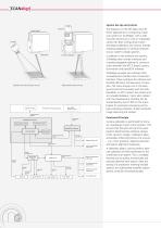
System Set-Up and Control The diagrams on the left depict two different approaches to configuring a laser scan system for SCANalign: with a sidemounted camera (a) or with an integrated camera (b). Both configurations allow GUI-based calibration and control, thereby enabling adaptation of camera hardware to your system's design specifics. Scan head Camera adapter In addition to the software and camera, SCANalign also includes interfaces and complete pluggable cabling for communication between the RTC 5 board, camera, illumination and laserDESK software. SCANalign provides two software GUIs: a...
Open the catalog to page 2
SCANalign's Vision Engine automatically provides undistorted, correctly-scaled camera images – as shown top right. SCANalign vision jobs can automatically analyze these corrected images, e.g. for determining a workpiece's position and orientation using reference marks or other geometric properties of the workpiece. The Vision Engine provides analysis results that the laser scan application can use to align scan patterns relative to a workpiece's actual position and orientation. By creating this automation, SCANalign delivers optimal processing results while eliminating the need to precisely position...
Open the catalog to page 3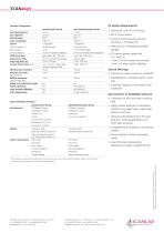
Example Configuration coaxial camera set-up side-mounted camera set-up Scan head aperture Scan objective Control board Laser wavelength Camera triggering hardware signal software signal Power supply Camera objective f = 8 mm (standard camera objective) Calibration plate Illumination / Filter Processing field size Camera field of view (max.) (16 x 13) mm2 single image, merged images possible 13 µm • PC internal power supply with 12 V and 5 V; - max. 0.5 A for camera and controls, - max. 2 A when used for lighting Service Offerings Absolute accuracies (by calibration) Relative accuracies (position...
Open the catalog to page 4All SCANLAB GmbH catalogs and technical brochures
 smart scanning
6 Pages
 intelliSCAN IV
4 Pages
 powerSCAN II 50i
2 Pages
 excelliSHIFT
1 Page
 dynAXIS 421
4 Pages
 Polygon Scanner Systems
2 Pages
 palmSCAN
2 Pages
 laserDESK
4 Pages
 intelliWELD II, intelliWELD
4 Pages
 basiCube
2 Pages
 basiCube14
2 Pages
 rtc4
rtc42 Pages
 powerscanpowerscani
4 Pages
 intelliscaniii
2 Pages
 intelliscanse
2 Pages
 intelliSCAN+intelliScande
4 Pages
 hurryscaniiihurryscan
4 Pages
 high-speed z axis
1 Page
 dynaxis
2 Pages
 CollimationModul
2 Pages
 excelliSCAN scan system
4 Pages
 Company Profile SCANLAB AG
24 Pages
 basiCube 10 scan head
2 Pages
 hand-held scan-device
2 Pages
 universal and compatible
4 Pages
 intelliSCAN III Scan Heads
2 Pages
 Galvanometer Scanners
2 Pages
 Scancube III Scan Heads
2 Pages
 Camera Adapter
2 Pages
 laserDESK Software
4 Pages
 RTC5 control boards
2 Pages
 Scan System "powerSCAN"
4 Pages
 Scan-System "intelliWELD"
4 Pages
 2D Scan Heads "hurrySCAN"
4 Pages




Archived catalogs
 SCANcube® 7, 8.5, 10, 14
2 Pages
 intelliSCAN®
2 Pages
 intelliWELD® 30 FC
2 Pages
 powerSCAN 33
2 Pages
 RTC®3, RTC®4
2 Pages
 RTC®5
RTC®52 Pages
 Camera Adapter
2 Pages


- Welding system
- Automation software solution
- Positioning table
- Automatic welding machine
- Windows software
- Translation stage
- Control software
- Motorized positioning table
- Interface software
- Quality software
- Laser welding machine
- Creation software
- Optimization software
- 3D scanning system
- Measurement scanner
- Laser scanner
- XY scanner
- Vertical positioning stage
- High-precision scanner
- Machining software