
- Catalogs
- SBC Linear
- SBI Ball guide


SBI Ball guide

SBI Ball guide
The document outlines the technical specifications and guidelines for the SBC Linear Rail System, focusing on its high rigidity, load capacity, and energy efficiency. It details structural features, maintenance benefits, and various models suitable for different machine designs.
The Circular-Arc raceway structure provides high rigidity and load capacity, featuring a four-row circular arc groove and two-point contact for uniform load distribution. The DF structure reduces instrumental errors and enhances energy efficiency. Models such as SBI, SBG, SBS, SPG, and SPS are highlighted for specific applications.
The document compares the Circular-Arc Groove with the Gothic-Arch Groove, highlighting the former's superior error absorption and smooth movement under high load conditions, while the latter is optimized for miniaturized machines.
The nominal life of the linear rail system is defined by the total travel distance before flaking occurs, with calculations based on load, dynamic load rating, and static load rating. Formulas for calculating static permissible moments and safety factors under various load conditions are provided.
The SBC linear rail systems have low static and dynamic coefficients of friction, minimizing driving force and temperature increase. Examples of frictional force calculations for different guide systems are included.
Guidelines for selecting the appropriate linear rail system consider machine structure, space, installation direction, stroke length, payload, velocity, and working environment.
Detailed procedures for calculating applied loads, equivalent loads, and mean loads are provided, considering various axis conditions and load directions.
Preload affects rigidity, internal load, and clearance. The document outlines preload conditions and their impact on rigidity, with examples for different machine applications.
Accuracy is defined by running parallelism, height, and width differences between blocks and rails. Accuracy levels are categorized into N, H, and P types.
Design guidelines include mounting methods, tolerance of mounting surfaces, and rail joint marking for long travel applications. Emphasis is placed on identifying reference surfaces and permissible tolerances to ensure smooth operation.
Steps include cleaning the mounting surface, applying spindle oil, positioning the rail and carriage plate, and tightening bolts with a torque wrench.
Involves clamping the reference rail, positioning the table with bearings, and tightening bolts carefully.
Lubrication is crucial for performance, reducing friction and wear. Oil with high thermal stability or grease with high viscosity is recommended. Application methods and intervals vary based on conditions.
Dust and rust prevention, along with re-lubrication, are necessary for longevity. Surface treatments like black chrome and fluorocarbon chrome coatings are available for anti-rust purposes.
RC caps prevent contaminants from entering bolt holes, with various seal options available based on conditions.
For temperatures above 80°C, high-temperature end-plates made of aluminum are recommended, with ST dustproof tape for rail face sealing.
DF seals provide dust protection, while MF containers offer self-lubrication for long maintenance intervals.
Various types are available, including high-load, standard, miniature, and low noise types, each with specific features and applications.
Grease fitting details and mounting restrictions for certain models are provided.
Catalog excerpts

Linear Rail System Technical Data Technical Data Circular-Arc raceway structure achieves the high rigidity and large permissible load. Four row circular arc groove with 2 points contact creates the same load in all directions. DF structure maintains low instrumental errors. DF structure maintains low instrumental errors. Ball Screw SBC LINEAR RAIL SYSTEM FEATURES Low frictional coefficient achieves the high energy efficiency. Easy maintenance. Improve the productivity of the machine. Support Unit Various options, Easy machine design and Longer life span. Comparison the Linear Rail System with others Linear Rail System Plane Ball System Sliding Friction Guide Additional working need Absorbing errors Machining necessary Various grease feeding Hard to grease feeding High rating load The Structure of Raceway Groove and Ball Contact Vulnerable to eccentric load Circular-Arc Groove, Four Raceway, Two-Point Contact Structure absorb the instrumental errors and create smooth movement even under high load operation. Cross Roller Guide Robot Carrer Guide Gothic-Arch Groove, Two Row, Four Point Contact Structure is not effective for absorbing errors but it is optimized for miniaturized machine which is necessary for smooth movement under high load condition. Applied Model: SBM, SBML, SBMW
Open the catalog to page 1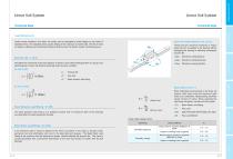
Linear Rail System Technical Data Technical Data Ball Screw Load Rating & Life Static Permissible Moment : Mo ( kN.m) Under normal conditions, the linear rail system can be damaged by metal fatigue as the result of repeated stress. The repeated stress causes flaking of the raceways and steel balls. The life of linear rail system is defined as the total travel distance that the linear rail system travels until flaking occurs. These load are maximum moments or torque loads that can be applied to the bearing without damaging the bearing or affecting subsequent dynamic life. Mro : Moment in rolling...
Open the catalog to page 2
Linear Rail System Technical Data Technical Data The procedure of selecting linear rail system The static and dynamic coefficient of friction of the SBC linear rail systems are so small that they minimize the required driving force and temperature increase. Frictional force depends on load, preload, velocity and lubrication. In general, the light load with high speed is more affected by the lubricant, while the medium or heavy load are more affected by the load and are less sensitive to lubrication selection. *Coefficient of friction for linear rail system( ) : 0.002~0.004 - Machine structure...
Open the catalog to page 3
Linear Rail System Technical Data Technical Data Calculating the applied loads and life time Horizontal axis Horizontal axis with overhung Ball Screw Select the system / Model Select the appropriate guide system after considering rigidity, cost of machine and manufacturing time. 2. Select Model Support Unit Select the few models based on simple calculation, space and experience. 3. Calculate the load and life time Cross Roller Guide Judge the expected life time after calculating the load and life time and apply the model to machine design. 3-1. Calculating the applied loads Loads exerted on a...
Open the catalog to page 4
Linear Rail System Technical Data Technical Data Horizontal axis with rail movable Vertical axis with wall mounted Lateral axis Support Unit Vertical axis Ball Screw Cross Roller Guide Robot Carrer Guide Memo
Open the catalog to page 5
Linear Rail System Technical Data Longitudinal axis Ball Screw Technical Data Horizontal axis with inertia Acceleration Cross Roller Guide Robot Carrer Guide Memo
Open the catalog to page 6
Linear Rail System Technical Data Technical Data 3-3. Static Safety Factors (fs) Linear Rail Systems can accept normal and moment (Mro, Mpo, Myo) loads in all directions including radial, reverse-radial and lateral loads at the same time. Therefore, calculate the equivalent load accordingly. When calculating a load exerted on the linear rail system, both mean and maximum load need to be considered. Reciprocating machines create moment of inertia. When selecting the right linear rail system, consider all of loads. Radial load Reverse-radial load is large Mro Moment in rolling direction Moment...
Open the catalog to page 7
Linear Rail System Technical Data Technical Data Loads acting on a linear rail system can vary according to various conditions. All load conditions must be taken into consideration in order to calculate the required linear rail system capacity Ball Screw 3-4. Calculating the Mean Load 3) Loads varying sinusoidally [Equation for calculating the mean load] Pm : Mean load Ln : Length of travel carrying Pn Mean load Varying load Total length of travel Length of travel carrying Pn 2) Loads that vary linearly Pmin : Minimum load Pmax : Maximum load Cross Roller Guide Support Unit L : Total length of...
Open the catalog to page 8
Linear Rail System Technical Data Technical Data The equation of nominal life for linear rail system is shown as below. [Calculation of nominal life] When two or more blocks are used in close contact, it is hard to obtain a uniform load distribution because of mounting errors and tolerances. The basic dynamic load C should be multiplied by the contact factors fc shown here. : Contact factor Normal condtion : Temperature factor : Hardness factor : Load factor Load factor (fw) Reciprocating machines create vibrations. The effects of vibrations are difficult to calculate precisely. Refer to the...
Open the catalog to page 9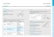
Linear Rail System Technical Data Technical Data Ball Screw The block side to side movement by vibration is called clearance. When the load is applied to Linear Rail Systems, the balls, blocks and rails experience the elastic deformation within permissible range. The ratio of displacement is known as the rigidity. The rigidity increases as the preload increases. Clearance checking In case of four way equal load type, the preload is available until the load increases to some 2.8 times the preload applied. Where rigidity is required, vibration and impact are present. Example Machining center Engineered...
Open the catalog to page 10
Linear Rail System Technical Data Technical Data Mounting method, tolerance of the mounting sufraces, and order in which the rails are mounted all affect the accuracy of machine,. Therefore we recommend considering below conditions. 6-1. Identifying reference surface [Master linear rail system] [Rail joint marking] For extremely long travel applications it may be necessary to join the rails via a butt joint. These joint are matched for continuous smooth motion at the factory and numbered. When installing the segments insure that the numbers at the joints match. In the case of a double rail system...
Open the catalog to page 11All SBC Linear catalogs and technical brochures
 SBR Roller guide
7 Pages
 Rolled Ball Screw
34 Pages
 Support Unit
13 Pages
 Robot Carrier Guide
11 Pages
 Cross Roller Guide
11 Pages
 SBC Linear - General Catalog
124 Pages
 SBM Miniature Guide
7 Pages
- Linear motion system
- Ball bearing linear guide
- Slide carriage block
- Compact linear guide
- Metal ball screw
- Roller linear guide
- Precision ball screw
- Rolled ball screw
- Heavy load linear guide
- Wide linear guide
- Adjustable carriage block
- Miniature linear guide
- High-rigidity linear guide
- High-rigidity ball screw
- Flange linear guide
- Zero-backlash ball screw
- Low-profile linear guide
- Machine tool linear guide