
Catalog excerpts

Product Information PI 49 e Disc-type tool turret without tool drive 0.5.480.5xx with tool drive (axial)
Open the catalog to page 1
Please request the following document if required: PI 18 configuration instructions The information contained in this Product Information is based on the knowledge available at the time of printing. We reserve the right to perform modifications within the framework of continuous further development.
Open the catalog to page 3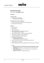
Disk-type tool turret Without tool drive 0.5.480.5xx series Description Tool turret series Without tool drive 0.50.480.5xx ▪ With axial or radial tool holder The approved tool turret is suitable for Use on turning machines for forward and reverse machining. Medium-sized series production Features Robust structure Simply control Short switching times Electromechanical drive for swivelling and locking, thus no additional medium required Use of absolute encoders – no reference point travel required High degree of stability due to high locking forces Locking with special three-part Hirth...
Open the catalog to page 4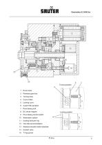
Drive motor Turning drive Curve rollers Locking curve Pre-indexing bolt Pre-indexing control switch Attenuation system Tool disk accommodation Absolute encoder switch absolute Coolant valve Cooling lubricant ring Locking position
Open the catalog to page 5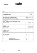
Technical Data Technical Data Series Disk-type tool turret 0.5.480.5xx Number of switching positions Admissible tangential load (turret locked) Adm. moment of inertia (tool disk and tool holder1)) Admissible out of balance (load moment) due to tooling Switching times Rotating 2) tool disk (incl. unlocking, rotating tool disk, locking) 30° per step (12-fold) Adm. switching frequency (average switch angle ϕm = 90°) 2) 30° per step (12-fold) 45° per step (8-fold) Mass Mass (without tool disk) Medium pressure valve High-pressure cooling lubricant supply Admissible ambient temperature
Open the catalog to page 6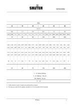
Technical Data 7 – 14 (without filtering) 5 .. 25 (filtering < 100 µm) 100 (filtering < 25 µm) 10 ... 40 1) Further values for moment of innertia and switching times on request 2) The values are valid for 50 Hz operation; deviations of ± 5 % are possible for 60 Hz operation.
Open the catalog to page 7
(reference values) Note: The diagrams refer to static load. In the case of impact loads (interrupted cutting) much lower values must be expected.
Open the catalog to page 8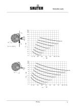
Admissible Loads Size 40 Size 32 Size 25 Size 20 Size 16 Size 12 Size 10 Size 40 Size 32 Size 25 Size 20 Size 16 Size 12 Size 10
Open the catalog to page 9
Selection of the Tool Turret Size Selection of the tool turret size (reference values) Example Given machine rating P Desired cutting cross-section A Tool overhang r Result: Size Size 40 Size 32 Size 25 Size 20 Size 16 according to machine power at v = 200 m/min Machine power Tool overhang Size 40 Size 32 Size 25 Cutting cross-section according to cutting cross-section at St 60 (ks = 2200 N/mm2) Size 20 Size 16 Size 12 Size 10 Tool overhang
Open the catalog to page 10
Disk-type tool turret 0.5.480.xxx
Open the catalog to page 11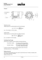
Precision Fluid Rotary Feed-Though Control Unit EK 502 Repeating accuracy (Multiple approach of a switching position from the same direction) e.g. ± 0.8 µm based on a 100 mm radius Indexing position (Multiple approach of a switching position from different directions) Fluid Rotary Feed-Through Die Revolver sind lieferbar mit einer zentralen Fluid-Drehdurchführung: “Uncontrolled” variation - Fluid supply in all switching positions e.g. for sealing air, for gripper actuation “Controlled“ variation - Fluid supply in one switching position e.g. for KSS, automatic tool change A maximum of three...
Open the catalog to page 12
Disk-Type Tool Turret 0.5.473.5xx series with Axial Tool Drive Description These turrets have a modular design. They consist of a basic turret from the 0.5.480.5xx series and a decentralized tool drive mounted in place of the cooling lubricant ring. The tool drive has been designed for individually switchable, axially placed tools for forwards machining. The tool drive motor drives the coupling wheel via the spur gear incorporated in the gearbox casing. The relevant tool is switched into the working position by means of the coupling. The drive motor can be located to the side opposite the...
Open the catalog to page 13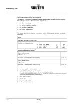
Perforamance Data Performance Data on the Tool Coupling The gearbox is designed for the performance data indicated below for the tool coupling. The actually available performance data depends on: the drive motor used the speed on the tool coupling the duration of activation the cutting performance The values given in the following examples of cutting efficiency can be taken as reliable estimates Series Disk-type tool turret 0.5.473.5xx Gearbox performance data ▪ ▪ ▪ Adm. drive rating 1) Adm. torque 2) Adm. speed 3) Padm Madm nadm Recommended drive motors 5) Siemens servomotor Type 1 FT 6.....
Open the catalog to page 14
Performance Data
Open the catalog to page 15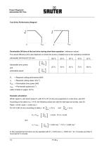
Power Diagramm Admissible ON Time Tool Drive Performance Diagram Permissible ON time of the tool drive during short-time operation (reference values) The actual efficiency (DC) also depends on where the turret is installed and on the operating conditions! Admissible ON time [OT] (5 min) Admissible drive power and admissible speed = Required cutting performance [kW] = Required cutting speed [min-1] Padm = Permissible drive power [kW] nadm (refer to table on pages 14/15) Example calculation: Which speed nc and which power Pc with 40 % OT (5 min) are supported on a tool drive, size 20?...
Open the catalog to page 16
Cutting Efficiency Cutting performance in steel St 60 Blunting factor -1.6 on the tool Examples (non-binding reference values) Disk-type tool turret 0.5.473.5.xxx Drilling HSS spiral drill Drilling HM short hole drill Threaddrilling Keyway cutting Finger milling Keyway cutting Disc cutting
Open the catalog to page 17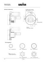
Design Varianten Tool Arrangement Possible motor arrangement: position 9°° or 12°° Alternate Configurations Working position d1 X (the cw turret type is shown) Tool Arrangement Position with tool drive Position without tool drive
Open the catalog to page 18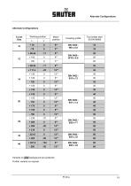
Alternate Configurations Alternate Configurations Working position Turret Size Tool holder seat Ø DIN 69880 16 16 20 20 Variants on grey background are preferred Further variants on request
Open the catalog to page 19All Sauter Feinmechanik catalogs and technical brochures
-
 Sauter Rotary Table RT Lines
1 Pages
-
 Sauter Test Equipment
1 Pages
-
 PI 21.3
34 Pages
-
 PI 42
PI 4251 Pages
-
 PI 46
PI 4623 Pages
-
 The pti working group presents
12 Pages
-
 Motor spindle
1 Pages
-
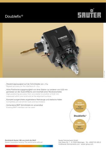 Doublefix®
1 Pages
-
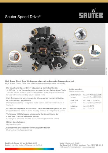 Sauter Speed Drive®
1 Pages
-
 Sauter Torque Drive®
1 Pages
-
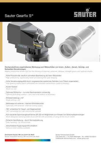 Sauter Gearfix S®
1 Pages
-
 Sauter Double-Seal-Line
1 Pages
-
 Modifix®
1 Pages
-
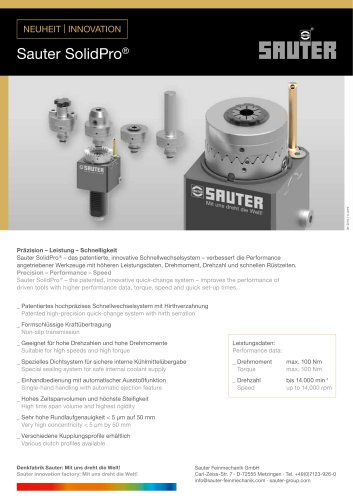 Solidpro
1 Pages
-
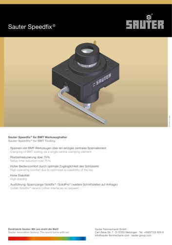 Speedfix
1 Pages
-
 BMT Tooling
1 Pages
-
 PI 62
PI 6223 Pages
-
 PI 43.2
36 Pages
-
 PI 52
PI 5224 Pages
-
 PI 31.2
50 Pages
-
 PI 25.3Crown-type turrets
33 Pages
-
 PI 01 Head-type turrets
27 Pages


Archived catalogs
-
 R 63: The world turns with us
16 Pages

