- Catalogs
- SATEL IBERIA
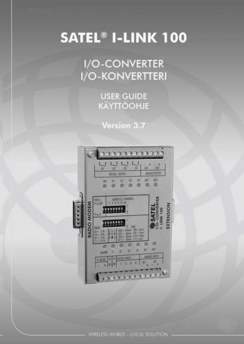
- SATEL I-LINK 100
SATEL I-LINK 100
1 /21Pages
SATEL I-LINK 100
1 /21Pages
Catalog excerpts
USER GUIDE KAYTTOOHJE
Open the catalog to page 1
SATEL, I-LINK100 I/O-converter User Guide, Version 3.7
Open the catalog to page 2
SATEL, I-LINK100 I/O-converter User Guide, Version 3.7 IMPORTANT NOTICE All rights to this manual are owned solely by SATEL Oy (later called also SATEL). All rights reserved. The copying of this manual without the written permission from the owner of the rights by printing, copying, recording or by any other means or the full or partial translation of the manual to any other language including all programming languages using any electrical, mechanical, magnetic, optical, manual or other methods or devices is forbidden. SATEL reserves the right to change the technical specifications or functions...
Open the catalog to page 3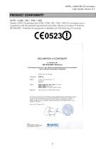
SATEL, I-LINK100 I/O-converter User Guide, Version 3.7 Hereby, SATEL Oy declares that SATEL I-LINK 100 / 200 / 300 I/O-converters are in compliance with the essential requirements and other relevant provisions of Directive 89/336/EEC. Therefore the equipment is labelled with the following CE-marking. DECLARATION of CONFORMITY In Accordance with 89/336/EEC Directive of the European Council of 3rd May 1989 on the approximation of the laws of the Member States relating of electromagnetic compatibility Doc No: SATEL-DC-EMC-089 Manufacturer: SATEL l-LINK 100 / 200 / 300 I/O Converters SATEL C-LINK...
Open the catalog to page 4
SATEL, I-LINK100 I/O-converter User Guide, Version 3.7 WARRANTY AND SAFETY INSTRUCTIONS Read these safety instructions carefully before using the product: Warranty will be void, if the product is used in any way, which is in contradiction with the instructions given in this manual, or if the housing of the radio modem has been opened or tampered with. The radio modem is to be used only on frequencies allocated by local authorities and without exceeding the given maximum allowed output power ratings. SATEL is not responsible, if any products manufactured by it are used in unlawful ways. The devices...
Open the catalog to page 5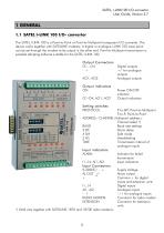
SATEL, l-LINKl 00 l/O-converter User Guide, Version 3.7 1.1 SATEL l-LINK 100 I/O- converter The SATEL l-LINK 1 00 is a Point-to-Point or Point-to-Multipoint transparent l/O-converter. The device works together with SATELLINE modems. A digital or analogue l-LINK 1 00 input-point can be set through the modem to be output in the other end. Point-to-Multipoint transmission is possible adopting software suitable for the SATEL l-LINK 100. Output Connectors 01...04 - +AO 1, A02Output indicatorsON01-04, AOl, A02Setting switchesPROTOCOL Digital outputs +/- for analogue outputs Analogue outputs Power ON/OFF...
Open the catalog to page 6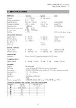
SATEL, I-LINK100 I/O-converter User Guide, Version 3.7 Power consumption Serial Interface Extension Interface Response time Operational temperature Transfer rates Stability Inputs, 2 pcs Outputs, 2 pcs Sample interval Resolution Accuracy note active RS232 active TTL @ 9600 bps @ for whole temp. range resistive 4-5 kQ relay contacts INDICATORS Indicators Power ON/OFF, digital/analogue IN/OUT, Alarm Alarm Output 0 - 35 Vdc / 30 mA 24 Vdc / 20 mA active + 30 mA Modem compatibility Stainless steel In the fail-state all I/O-points remain unchanged D-1 5 for SATELLINE radio modem, D-1 5 for the extension...
Open the catalog to page 7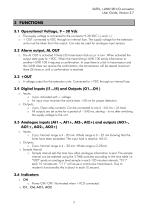
SATEL, I-LINK100 I/O-converter User Guide, Version 3.7 3 FUNCTIONS 3.1 Operational Voltage, 9 – 30 Vdc o The supply voltage is connected to the connector 9-30 VDC (-) and (+). o + OUT connected to VDC through an internal fuse. The supply voltage for the extension units must be taken from this output. Can also be used for analogue input sensors. 3.2 Alarm output, AL OUT o The AL OUT is activated if three (3) transmission fails occur in turn. When activated the output state goes to +VDC. When the transmitting I-LINK 100 sends information to another I-LINK 100 it requires a confirmation. In case...
Open the catalog to page 8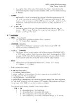
SATEL, I-LINK100 I/O-converter User Guide, Version 3.7 o Showing the status of the output. Illuminated when there is information on the output. Flashing when range has been exceeded. OFF, when low state or nothing on the input. o Illuminated, if a fail in transmission has occurred. When the transmitting I-LINK 1 00 sends information to another I-LINK 1 00 it requires a confirmation. In case there is a fail in transmission and the I-LINK does not receive the confirmation, the transmission will be resent maximum three (3) times or until a confirmation is received. o I1...I4, Ail, AI2 o Showing...
Open the catalog to page 9
SATEL, I-LINK100 I/O-converter User Guide, Version 3.7 o 5 HS For setting CTS-control (clear to send) On or OFF 1 = CTS OFF, 0 = CTS ON. Defines how often the analogue input message is transmitted. The intervals are follows:
Open the catalog to page 10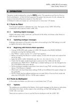
SATEL, I-LINK100 I/O-converter User Guide, Version 3.7 4 OPERATION Operation mode is selected by using the PRTCL-switch. The operations are Point-to-Point or Point-to-Multipoint. In Point-to-Point operation the system has one pair of units, whereas the inputs at one end will became outputs on the other end. In Multipoint mode one master can command one or more (max 127) slaves. 4.1 Point-to-Point Point-to-point operation is between two units. The inputs of one I-LINK 100 will be transferred to the outputs of other I-LINK 100. 4.1.1 Updating digital messages Digital information (relay, switch...
Open the catalog to page 11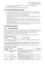
SATEL, I-LINK100 I/O-converter User Guide, Version 3.7 1. You can have your own system and program and integrate I-LINK 1 00 into it; the commands are described below. 2. You can have an easy-to-use SATEL I-LINK PC-software. o Connect one SATELLINE radio modem to the PC COM-Port. This one is the Master unit. o Connect the I-LINK 1 00 Slave-units to the SATELLINE radio modems directly to I-LINK 1 00 Radio Modem connector or using a interface cable o The "PRTCL"- switch must be "1 ", in the P-to-MP-position. o Before connecting the device to a power supply, connect first all inputs and outputs...
Open the catalog to page 12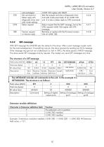
User Guide, Version 3.7 Example: 3 extension modules installed, I-LINK 200 + I-LINK300 + I-LINK 200 -> Extension field value =121.
Open the catalog to page 13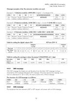
SATEL, I-LINK100 I/O-converter User Guide, Version 3.7 Message examples when the extension modules are used. Example A: 1 Extension module, I-LINK 200 (4 digital + 2 analogue I/O) The equipment that has received a GET or SET request, will answer with an ACK-message.
Open the catalog to page 14All SATEL IBERIA catalogs and technical brochures
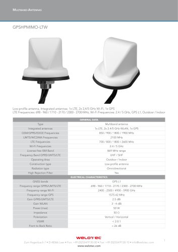 GPSHPMIMO-LTW
2 Pages
 MISSION-CRITICAL CONNECTIVITY
154 Pages
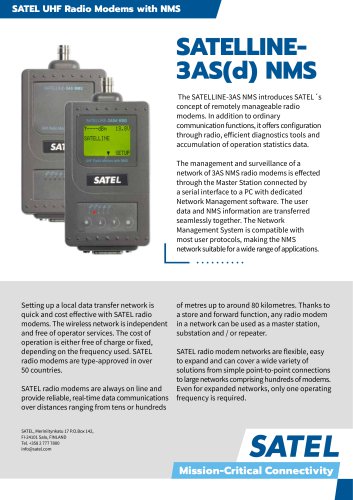 SATELLINE3AS(d) NMS
2 Pages

- Ethernet communication router
- DIN rail communication router
- Serial converter
- GNSS antenna
- Data communication router
- Outdoor antenna
- RS232 communication router
- RS485 communication router
- IP67 antenna
- WLAN antenna
- RS-232 converter
- GPS antenna
- LTE antenna
- RS232 modem
- Data modem
- WiFi antenna
- IP communication router
- VDSL2 communication router
- USB communication router
- Ethernet modem