Catalog excerpts
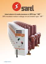
Interruttore di media tensione in SF6 tipo MF ӓ SF6 insulated medium voltage circuit breaker type MF ӓ > by size="-1">
Open the catalog to page 1
tr.row {} td.cell {} div.block {} div.paragraph {}
Open the catalog to page 2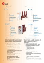
1. Designazione 1. Name 2. Reference standards and tests 2.1. 2. Norme di riferimento e prove Certified type tests at CESI (Centro Elettrotecnico Sperimentale Italiano - Italian Experimental Electrotechnical Committee) Gli interruttori della serie MF sono conformi alle norme IEC 62271-100 e IEC 60694 ed hanno superato le deguenti prove relative agli interrutori di classe M1: The circuit-breaker of the MF series comply with IEC 62271-100 and IEC 60694 standards and have passed the following tests for class M1 circuit-breaker: > Prove di tipo certificate presso il CESI (Centro Elettrotecnico...
Open the catalog to page 4
Prove individuali di collaudo in fabbrica 2.2. Individual testing at the factoryA test certificate is drawn up for each circuitbreaker including the following tests: Per ogni interruttore viene redatto un certificato di collaudo comprendente le seguenti prove: > Prova di isolamento a frequenza desercizio dei circuiti principali e dei circuiti ausiliari > Insulation test at power frequency for the main and the auxiliary circuits > Misura della resistenza dei circuiti principali > Main circuit resistance measurement > Prova di funzionamento meccanico > Mechanical operation test > Prova di...
Open the catalog to page 5
They are used for secondary medium voltage distribution and in medium voltage-low voltage transformation cabins.They are especially suitable for air/SF6 hybrid cabins, allowing an advantageous use of the space and an optimum distribution of the electric fields into the cabin components.In particular, the circuit-breaker of the MF 24P series with max current protection self-powered by 3 toroidal current transformers allow use also in case of auxiliary power failure.Thanks to the system of locks provided into the operating mechanism, to the high quality microswitches and to the self-cleaning...
Open the catalog to page 6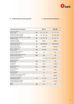
6. Caratteristiche tecniche generali 6. General technical features 5 >
Open the catalog to page 7
7. Altitudine 7. Altitude Internal parts of equipment insulated with SF6 are not influenced to altitude variations.For external parts insulated in air, the dielectric streng of the external insulation is affected by the air proper-ties, humidity, density, etc.When height above seal level increases, air density and dielectric power decrease.This should be taken into account in the design of an equipment insulation, when the minimum installation distance is set at a height of over 1000 m above sea levelCorrection procedure:Method 1:Knowing the altitude H of the place, find the corresponding...
Open the catalog to page 8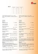
Livelli disolamento standard 1kV < Um < 52kVLista 1 e lista 2 (selezione in relazione al grado di rischio) Standard insulation levels 1kV < Um < 52kVList 1 and list 2 (selection according to the risk factor) Esempio.Metodo 1: Example.Method 1: Altitudine del luogo H = 2000mFattore di altitudinericavato dalla fig. A K = 0.89Massima tensione per lҒapparecchio Um = 17.5 kVDeterminazione del livello di isolamento (fig. B):tensione impulso UrB = 95 kVTensione a frequenzaindustriale UrW = 38 kVIl livello di isolamento richiesto ad unaltitudine di 2000m s.m.l.Ҩ pertanto:tensione impulso UrB = 95 /...
Open the catalog to page 9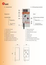
8. Comando M 200 8. M 200 operating mechanism > Energia 200 JTipo meccanicoa molla Energy: 200 JType mechanical operating mechanism > 1 Leva carica manuale 1 Manual loading lever 2 Contamanovre 2 Operating counter 3 Indicatore carica molla chiusura 3 Making spring load indicator 4 Blocco chiave 4 Key lock 5 Manipolatore di apertura 5 Breaking knob 6 Manipolatore di chiusura 6 Making knob 7 Indicatore carica molla apertura 7 Breaking spring load indicator 8 Indicatore posizione interruttore C/O 8 C/O circuit breaker position indicator 9 Rel di protezione max corrente 9 Max current protection...
Open the catalog to page 10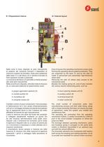
8.1 Disposizione interna 8.1 Internal layout > Zone A houses the operating mechanism power parts forming the operating device (patent-protected). They are supported by the base (1) and by the side (2) made of galvanised and passivated high-thickness sheet steel.Removing the side (2) allows easy access to the mechanical parts.Besides the making spring (4), zone B also includes the various electric interlocking parts, such as: Nella zona A sono disposte le parti meccaniche di potenza del comando formanti il dispositivo di manovra (coperto da brevetto). Esse sono sostenute dalla base (1) e dal...
Open the catalog to page 11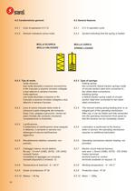
8.2 Caratteristiche generali 8.2 General features 8.2.1 Ciclo di operazioni O C O8.2.2 Simbolo indicatore carica molla 8.2.1 O C O operation cycle8.2.2 Symbol indicating that the spring is loaded MOLLA SCARICA MOLLA CARICA MOLLA UNLOADED 8.2.3 Type of springs: SPRING LOADED making spring: two concentric helical traction springs made of circular-section steel wire connected to two sheet steel connections. breaking spring: a helical traction spring made of circular- section steel wire connected to two sheet steel connections.8.2.4 The manual making spring loading lever is an integral part of...
Open the catalog to page 12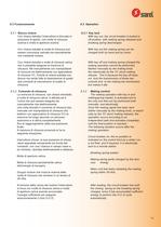
8.3 Funzionamento 8.3 Operation 8.3.1 Key lock With key out, the circuit breaker is locked in off position, with making spring released and breaking spring descharged. With key out the making spring can be charged both by hand and by motor. With key off and making spring charged the making operation cannot be performed. Neither manually by the making knob. Nor electrically by the YC shunt making release . This is because the key off does not lock the transmission of these two controls and to the making trip mechanism, but makes it idle8.3.2 8.3.1 Blocco chiave: Con chiave estratta...
Open the catalog to page 13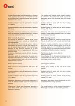
The breaking and making spring loaded condition is indicated on the control front and if required for the making spring, it is electrically sent to a remote station.Auxiliary contact in series with the shunt making release (YC): open Auxiliary contact in series with the shunt breaking release (Y1): closedMechanical anti-closure device positioned so as to disable a further making operation both if con trolled electrically and manually 8.3.3 Breaking control: the breaking operation is active and is the only one that can be performed both manually and electrically.Once the breaking control has...
Open the catalog to page 14All SAREL catalogs and technical brochures
-
IM6
16 Pages
-
SYSclad
20 Pages
-
Power Transformers
16 Pages
-
Oil Transformers
8 Pages
-
WL
28 Pages
-
IM6-PM
20 Pages
-
RMSYS
24 Pages
-
SYSTEM 6
24 Pages
Archived catalogs
-
Medium voltage insulator
4 Pages
-
OIL TRANSFORMERS
10 Pages


