
- Catalogs
- Sapag Valves
- PRESSURE RELIEF VALVE
PRESSURE RELIEF VALVE

PRESSURE RELIEF VALVE
This document is the exclusive property of SAPAG VALVES and provides indicative information about their industrial valves.
Performance Specifications
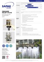
The performance of the valves is dependent on the pressure/temperature ratio, materials, size (DN), and the nature of the fluid. The valves are designed to limit maximum pressure by briefly discharging high flow.
Technical Features
- Metal-to-metal sealing between nozzle and blanking plate.
- Quick opening in 1/40th of a second.
- Adjustable setpoint via a spring acting directly on the blanking plate.
- Low inertia moving parts.
- Sealing for upstream pressure below setpoint.
- No guidance to prevent jamming or parasitic drag.
- Complete flow discharge with high precision and tightness.
- Safe actuation.
Conditions of Use
- Suitable for contaminated, raw, or drinking water.
- Installed downstream from pumping station pumps or upstream from a shut-off device or overspeed valve.
- Used in meshed networks with numerous nodes, especially where surges or bursts may occur.
Installation Guidelines
- Valves should be fitted vertically.
- Position as close as possible to the component causing pressure surges.
- Piping connector diameter should be at least equal to the pressure relief valve diameter.
Pressure Relief Valve Specifications
The valve operates effectively between -196°C and 700°C, with a maximum pressure of 100 bar. Specific diameter and pressure ratings are provided for different DN sizes.
Parts List
The document includes a detailed parts list with materials such as S235 JR, galvanized steel, X20Cr13, 17-4 PH, stainless steel, spring steel, and rubber.
Operating Instructions
Instructions for operating the valve 125/32 according to its set pressure are provided, including zones indicating maximum opening and spring wire diameter adjustments.
Conclusion
This document outlines the specifications, technical features, conditions of use, installation guidelines, and operating instructions for SAPAG VALVES' pressure relief valves, ensuring optimal performance and safety.
Catalog excerpts
SAPAG-0036-ENG-2302 The maximum pressures and temperatures depend on the pressure/temperature ratio, materials, size (DN) and nature of the fluid. Performance PRESSURE RELIEF VALVE Limit maximum pressure in a line by discontinuously and briefly discharging high flow. PROTECTING PIPES FROM PRESSURE SURGES Metal-to-metal sealing between nozzle and blanking plate. Quick opening: 1/40th of a second. Adjustable setpoint via spring acting directly on blanking plate. Moving part low inertia. Sealing for upstream pressure below setpoint. No guidance (no jamming or parasitic drag). Tightness and high-precision (honed radius). Safe actuation. Technical features Type of conveyed liquid: • Conditions of use Contaminated, raw or drinking water. In meshed networks with numerous nodes. Generally where surges/bursts may occur. Vertically fitted valve. As close as possible to the component creating pressure surges. Upstream from a shut-off device (valve) or overspeed valve. Downstream from pumping station pumps. Piping connector diameter at least equal to pressure relief valve diameter. FOLLOW-UP & ADVICE SAPAG VALVES FABRICANT FRANÇAIS DE ROBINET INDUSTRIEL 2 Rue du Marais 80400 Ham, FRANCE +33 (0)3 23 81 43 00 [email protected] w w w. s a p a g - v a l v e s . c o m Ce document est la propriété exclusive de SAPAG VALVES, l’usage, la reproduction, la communication à des tiers de ce document doivent faire l’objet d’une autorisation écrite préalable de notre part. Les informations contenues
Open the catalog to page 1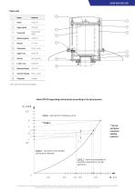
SAPAG-0036-ENG-2302 Parts List Name Upper plate Galvanized steel Blanking plate Stop plate Stain. steel Spring steel Bearing flange Counter flange Stain. steel Ring seal Other optional materials available Valve 125/32 operating instructions according to its set pressure H , m CE ZONE 1 : spring with contiguous turns ** ZONE 4 ** Do not set above maximum sealing pressure. ZONE 3 : Use device with smaller spring wire diameter. ZONE 2 : Valve has exceeded its maximum opening for correct operation. Q , L /s Ce document est la propriété exclusive de SAPAG VALVES, l’usage, la reproduction, la communication...
Open the catalog to page 2All Sapag Valves catalogs and technical brochures
 ISOBOX
2 Pages
 V574 - V575 - V576
2 Pages
 V16 BALL VALVE GACHOT
2 Pages
 V15
V152 Pages
 V10
V102 Pages
 V9-V29-V59
2 Pages
 V7
V72 Pages
 V3
V32 Pages
 DISCOVANNE
6 Pages
 MONOVAR®
2 Pages
 RMI DUBEX
2 Pages
 ELECTRIC ACTUATOR
2 Pages
 JMT
JMT2 Pages
 JMC COUNTERWEIGHT
2 Pages
 JMC
JMC2 Pages
 JHP
JHP2 Pages
 STRAINER
2 Pages
 V16 MODULAR SYSTEMS GACHOT
2 Pages
 V16 Gachot® Ball Valve
20 Pages
 DR / SR PNEUMATIC ACTUATOR
2 Pages
 V501 GATE VALVE GACHOT®
2 Pages
 CLASAR® CHECK VALVE
2 Pages
 V16 BALL VALVE GACHOT®
2 Pages
 Butterfly Valve
24 Pages
- Manual valve
- Stainless valve
- Ball valve
- Actuator
- Flange valve
- Liquid filter
- Flap valve
- Check valve
- Lever valve
- Standard valve
- Valve for the chemical industry
- Metal check valve
- Carbon steel valve
- Stainless steel pre-filter
- Compact actuator
- 3-way valve
- Stainless steel check valve
- Valve for the petroleum industry
- Heating valve