
- Catalogs
- SANYO DENKI EUROPE
- SANMOTION K

- Company
- Products
- Catalogs
- News & Trends
- Exhibitions
SANMOTION K

SANMOTION K
Catalog excerpts
Input voltage Servo motor Flange size Rated output Complies with EN,UL (cUL) Standards All the products in this catalog comply with CE/EN standards and cUL as standard. Complies with the EU Restriction of Hazardous Substances (RoHS) Directive All the products in this catalog comply with concentration limits for the specified hazardous substances (cadmium, lead, mercury, tetravalent chromium, PBB, PBDE, DEHP , BBP DBP and DIBP) listed in Appendix II of the EU RoHS Directive (2011/65/EU). , ,
Open the catalog to page 2
System Configuration Example -p. 5
Open the catalog to page 3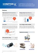
The SANMOTION K DC servo motors achieve smooth operation,high efficiency,and low noise. These motors are suitable for applications requiring high precision,including precision measuring instruments and medical equipment. Features High accuracy (Smooth operation) Cogging torque has been reduced by up to half compared with our conventional DC servo motors.* This enables smooth motor operation even at low speeds, improving the accuracy of equipment movements. Comparison of cogging torque waveforms Energy-saving (High efficiency) Power loss has been reduced by up to approximately 30% and efficiency...
Open the catalog to page 4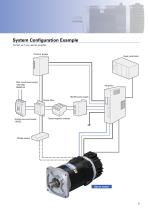
System Configuration Example Contact us if you need an amplifier. Control power Host controller Main circuit power supply 100 VAC 50/60 Hz 140 VDC power supply Noise filter Molded case circuit breaker (MCCB) Electromagnetic contactor Brake power Servo motor
Open the catalog to page 5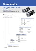
Low Cogging Torque, Low Loss, Low Noise Output capacity: 23 to 500 W For 42 and 54 mm motors, low-voltage (24 VDC) models are also available. ■ How to read model numbers Not all combinations of descriptions below are valid. For model numbers valid as standard products, refer to ‘Standard Model Number List.” K A 7 30 B S0 Incremental encoder
Open the catalog to page 7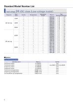
Standard Model Number List
Open the catalog to page 8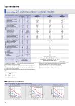
The values in the row with "☆" are for when the ambient temperature and armature winding temperature are 25°. The values in the row with "☆☆" are after thermal equilibrium is established. The values in the table above are for when operated with a stable DC current at ambient temperatures below 40°. The values for the tachogenerator are for when the test circuit shown below is used. Encoders can not be installed to KB4 models with a tachogenerator. The holding brake cannot be used for dynamic braking. Holding brakes are also available in 24 and 48 V. (Optional) Specifications are subject to change...
Open the catalog to page 10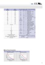
Servo motor model no. / Flange size / Rated output
Open the catalog to page 11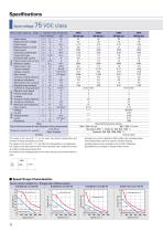
Servo motor model no. Inside ( > indicates motor flange size The values in the row with "☆" are for when the ambient temperature and armature winding temperature are 25°. The values in the row with "☆☆" are after thermal equilibrium is established. The values in the table above are for when operated with a stable DC current at ambient temperatures below 40°. The values for the tachogenerator are for when the test circuit shown below is used. Encoders can not be installed to KB4 models with a tachogenerator. The holding brake cannot be used for dynamic braking. Holding brakes are also available...
Open the catalog to page 12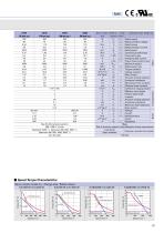
Servo motor model no. / Flange size / Rated output
Open the catalog to page 13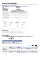
Motor Ground (Green / Yellow) (Orange) (Orange) Motor rotation direction When (Red): + and (Blue): counterclockwise as viewed from the output axis Tachogenerator polarity When rotating counterclockwise as viewed from the output axis, (Red): + and (Blue): -■Protection rating The protection ratings of our servo motors comply with IEC standards (IEC 60034-5 Edition 4.1, 2006-11). ■Compliance with International Standards and Directives European EC Directive (CE marking)
Open the catalog to page 14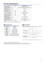
Lead wire color ■Output waveform •Line driver output (When rotating counterclockwise as viewed from the motor output shaft) A-channel output A-channel output B-channel output -B-channel output - Z-channel output — Z-channel output — (One pulse/rotation) Note: An open collector output type is also available as an option. T0 is the average time for one encoder rotation when the encoder is rotated at a constant speed. • Do not exert forces in the axial direction when handling. • Do not perform insulation resistance or dielectric strength testing as it may damage the electronic circuit. •The specifications...
Open the catalog to page 15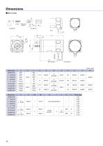
■Servo motor M Tapped hole Depth LT Motor lead wire Ground lead wire
Open the catalog to page 16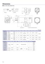
■Servo motor with tachogenerator M Tapped hole Depth LT Ground lead wire Tachogenerator lead wire Motor lead wire
Open the catalog to page 18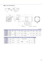
■Servo motor with holding brake M Tapped hole Depth LT Motor lead wire Ground lead wire Brake lead wire
Open the catalog to page 19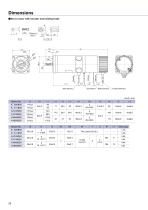
■Servo motor with encoder and holding brake M Tapped hole Depth LT Motor lead wire Ground lead wire Brake lead wire Encoder lead wire
Open the catalog to page 20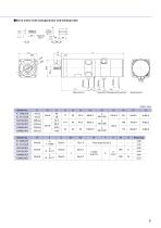
■Servo motor with tachogenerator and holding brake M Tapped hole Depth LT Motor lead wire Ground lead wire Tachogenerator lead wire Brake lead wire
Open the catalog to page 21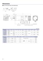
■Servo motor with encoder and tachogenerator M Tapped hole Depth LT Encoder lead wire Ground lead wire Tachogenerator lead wire Motor lead wire
Open the catalog to page 22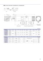
■Servo motor with encoder, tachogenerator,and holding brake M Tapped hole Depth LT Encoder lead wire Brake lead wire Ground lead wire Tachogenerator lead wire Motor lead wire
Open the catalog to page 23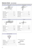
Ball screw Rack & pinion Workpiece External force | Workpiece External force Rack Workpiece + table mass W Ball screw diameter D Ball screw length L Ball screw lead P Ball screw density p Roll feed Belt drive Workpiece + belt mass W Pulley moment of inertia J Rotary indexing table Table support diameter Dh Table moment of inertia J Friction coefficient of table support p Gear ratio * G * Derivation of gear ratio (G) G2 Ball screw 7 imiiwnwnwiiwi), Number of screw threads (G2) Number of motor gear teeth (G1)
Open the catalog to page 24
Safety Precautions The products in this catalog are designed to be used with general industrial devices. Pay sufficient attention to the following: ・Read the Instruction Manual carefully prior to installation, assembly, or operation for the correct usage. The Instruction Manual is available for download from our website. ・Refrain from modifying or processing the product in any way. ・Contact your point of sale or specialized service provider for installation or maintenance services of the product. ・Consult with us when using the product for the following uses, as these require special considerations...
Open the catalog to page 25All SANYO DENKI EUROPE catalogs and technical brochures
 San_Ace_200_9GA_φ200x70
4 Pages
 SAN_ACE_120AD_120x25_ACDC
4 Pages
 San_Ace_40LG_40x28_Long_Life
4 Pages
 STEPPING MOTOR WITH ENCODER
32 Pages
 Company Profile 2023
8 Pages
 SANMOTION G
80 Pages
 San_Ace_140x38_9RA
4 Pages
 San_Ace_160ADW51
4 Pages
 San_Ace_160ADA51
4 Pages
 San_Ace_120ADAW38
4 Pages
 San_Ace_120ADA38
4 Pages
 San Ace 80x38 - 9RA
4 Pages
 San Ace 2022
632 Pages
 SANMOTION F2
84 Pages
 PRODUCT INFORMATION
52 Pages
 San Ace 100W
4 Pages
 San Ace 172AD
4 Pages
 San Ace 120 - 9RA
4 Pages
 San Ace 92 - 9RA
4 Pages
 San Ace 80 - 9RA
4 Pages
 San Ace 60 - 9RA
4 Pages
 San Ace 133W
4 Pages
 SANMOTION_R_3E_AC400V_550W-55kW
128 Pages
 SANMOTION C _ SMC100 _ECAT
12 Pages
 SANMOTION F5
128 Pages
 SANMOTION R
4 Pages
 San Ace Controller
4 Pages
 San Ace 97W
4 Pages
 SANMOTION R 100/200V General Catalog
172 Pages
 SANMOTION_R_AD_48VDC_20-200W
36 Pages
 Model No. PB
104 Pages
 SANMOTION_Linear
4 Pages
 SANMOTION_C_EtherCAT
16 Pages
 SERVOMOTOR_R2_14mm_2W
2 Pages
 DC SERVO SYSTEMS
36 Pages
 3 PHASE STEPPER - SANMOTION F3
12 Pages
 SANUPS HYBRID UPS E11A
8 Pages
 A11J
A11J12 Pages


Archived catalogs
 SANMOTION_C
12 Pages
 San Ace 150W
4 Pages
 San Ace 2018 ver. 2
576 Pages
 2-PHASE STEPPING SYSTEMS
100 Pages
 5-phase stepping MOTOR
128 Pages
 SERVOMOTOR_R2_275mm_37kW
2 Pages
 SANMOTION_R_100-200V_30W-1kW
40 Pages
 SANMOTION_R_3E_AD_100-200V_30W-30kW
160 Pages


- Electromotor
- DC electromotor
- Multipole motor
- 24 V motor
- Propeller fan
- Servo-motor
- 2-pole motor
- High-efficiency electromotor
- Servo-amplifier
- Stepper motor
- High-performance servo motor
- Motor controller
- AC servo-motor
- High-torque motor
- 48 V motor
- Custom motor
- DC servo-amplifier
- On-line UPS
- Cooling fan
- Fieldbus servo-drive