
- Catalogs
- SANYO DENKI EUROPE
- San Ace 80x38 - 9RA

- Company
- Products
- Catalogs
- News & Trends
- Exhibitions
San Ace 80x38 - 9RA

San Ace 80x38 - 9RA
This document is a technical catalog from SANYO DENKI CO., LTD., focusing on the specifications and guidelines for their DC fan models, particularly the 9RA type.
- Dimensions: The fan features a ribbed frame with a pulse sensor and PWM control function. Precise measurements for mounting holes and vent openings are provided.
- Pulse Sensors: The output waveform requires a pull-up resistor, with an open collector output circuit. Rated voltage specifications vary for 12/24 V and 48 V fans, with defined maximum values for VCE and Ic.
- Common Specifications: The fan's frame and impeller are made of plastic with specific flammability ratings. It includes motor protection functions, dielectric strength, insulation resistance, and sound pressure level details.
- Operating Conditions: The fan operates within a specified temperature range and has an expected lifespan based on continuous operation at rated voltage.
- Low Noise and Energy Saving: The fan reduces noise by 3 dB(A) and power consumption by 25.5% compared to previous models.
- Rich Lineup: Available in various voltages (12/24/48 V), cooling performance, noise levels, and PWM control options.
The document includes detailed graphs and data on airflow and static pressure for different models and operating conditions, highlighting the impact of PWM duty cycles.
PWM frequency is set at 25 kHz, allowing fan speed control via PWM duty cycle. Examples of PWM input signals and connection schematics are provided.
Users are advised to read the 'Safety Precautions' on the company's website before using the products. The products are subject to Japanese Export Control Law, and diversion contrary to the law is prohibited.
The catalog mentions features such as Electrolytic Corrosion Proof Fans and EMC guards to protect fan bearings against electrolytic corrosion near strong electromagnetic noise sources.
San Ace, SANUPS, and SANMOTION are trademarks of SANYO DENKI CO., LTD. The document also notes that company and product names are trade names or trademarks of their respective companies.
Contact details for SANYO DENKI CO., LTD. are provided, including their address in Tokyo, Japan, and a telephone number.
Catalog excerpts
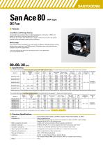
DC Fan ■ Features Low Noise and Energy Saving Compared to our current model,(1) noise level has been reduced by 3 dB(A) and power consumption has been reduced by 25.5%.(2) Moreover, the models with PWM control, which enables the control of fan speed, provide further optimized noise level and efficiency. Rich Lineup The product lineup is available in a wide variety in different 12/24/48 voltage, cooling performance, noise level, and PWM control. This allows users to choose the most suitable one for their applications. (1) Current model: 80 × 80 × 38 mm San Ace 80 9G type DC Fan (model: 9G0812G101). (2) For models 9RA0812G1001 The models listed below have ribs and pulse sensors with PWM control function. For models without ribs, append "1" to the end of model numbers. Model no. Operating voltage range [V] The models listed below have ribs and pulse sensors. For models without ribs, append "1" to the end of model numbers. Model no. Operating voltage range [V] Models with the following sensor specifications are also available as options: ■ Common Specifications □ Material □ Expected life Frame: Plastic (Flammability: UL 94V-0), Impeller: Plastic (Flammability: UL 94V-1) Refer to specifications (L10 life: 90% survival rate for continuous operation in free air at 60°C, rated voltage) Expected life at 40°C is for reference only. □ Motor protection function Locked rotor burnout protection, Reverse polarity protection 50/60 Hz, 500 VAC, for 1 minute (between lead wire conductors and frame) 10 MΩ min. at 500 VDC (between lead wire conductors and frame) □ Sound pressure level (SPL) A-weighted sound pressure level (SPL) at 1 m away from the air inlet. Refer to specifications (Non-condensing) + Red − Black Sensor Yellow Control Brown (For models without PWM control fu
Open the catalog to page 1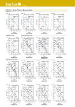
■ Airflow - Static Pressure Characteristics PWM duty cycle Static pressure Static pressure Static pressure Static pressure Operating voltage range (inch H2O) (Pa) 1.4 360 Static pressure Static pressure Static pressure Static pressure PWM duty cycle (inch H2O) (Pa) Operating voltage range Static pressure Static pressure Static pressure Static pressure Static pressure Static pressure Static pressure Static pressure
Open the catalog to page 2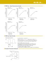
80× 80× 38 mm ■ PWM Duty - Speed Characteristics Example (min-1) 9000 ■ PWM Input Signal Example Input signal waveform PWM duty cycle (%) = T ×100 PWM frequency 25 (kHz) = T Current source (Isource) = 1.0 mA max. (when control voltage is 0 V) Current sink (Isink) = 1.0 mA max. (when control voltage is 5.25 V) When the PWM control terminal is open, the fan speed is the same as the speed at 100% PWM duty cycle. The PWM signal can be used with open collector or drain input. Note that when using an open collector or drain input, or inputting a different voltage or frequency, the speed relative to...
Open the catalog to page 3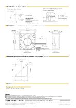
■ Specifications for Pulse Sensors Output waveform (Need pull-up resistor) Output circuit: Open collector In case of steady running Pull-up resistor Pull-up voltage Rated voltage 12/24 V fan VCE = +30 V max. Ic=10 mA max. [VOL=VCE (SAT)=0.6 V max.] Rated voltage 48 V fan VCE = +60 V max. Ic=10 mA max. [VOL=VCE (SAT)=0.4 V max.] ■ Dimensions (unit: mm) (Ribbed frame with pulse sensor with PWM control function) 80±0.5 71.5±0.3 Mounting hole (10) Lead wire AWG 26 (With PWM control function) AWG 24 (Without PWM control function) UL 1007 Rotating direction Airflow direction ■ Reference Dimensions of...
Open the catalog to page 4All SANYO DENKI EUROPE catalogs and technical brochures
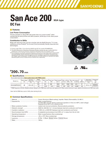 San_Ace_200_9GA_φ200x70
4 Pages
 SAN_ACE_120AD_120x25_ACDC
4 Pages
 San_Ace_40LG_40x28_Long_Life
4 Pages
 STEPPING MOTOR WITH ENCODER
32 Pages
 Company Profile 2023
8 Pages
 SANMOTION G
80 Pages
 San_Ace_140x38_9RA
4 Pages
 San_Ace_160ADW51
4 Pages
 San_Ace_160ADA51
4 Pages
 San_Ace_120ADAW38
4 Pages
 San_Ace_120ADA38
4 Pages
 San Ace 2022
632 Pages
 SANMOTION F2
84 Pages
 PRODUCT INFORMATION
52 Pages
 San Ace 100W
4 Pages
 San Ace 172AD
4 Pages
 San Ace 120 - 9RA
4 Pages
 San Ace 92 - 9RA
4 Pages
 San Ace 80 - 9RA
4 Pages
 San Ace 60 - 9RA
4 Pages
 San Ace 133W
4 Pages
 SANMOTION_R_3E_AC400V_550W-55kW
128 Pages
 SANMOTION K
28 Pages
 SANMOTION C _ SMC100 _ECAT
12 Pages
 SANMOTION F5
128 Pages
 SANMOTION R
4 Pages
 San Ace Controller
4 Pages
 San Ace 97W
4 Pages
 SANMOTION R 100/200V General Catalog
172 Pages
 SANMOTION_R_AD_48VDC_20-200W
36 Pages
 Model No. PB
104 Pages
 SANMOTION_Linear
4 Pages
 SANMOTION_C_EtherCAT
16 Pages
 SERVOMOTOR_R2_14mm_2W
2 Pages
 DC SERVO SYSTEMS
36 Pages
 3 PHASE STEPPER - SANMOTION F3
12 Pages
 SANUPS HYBRID UPS E11A
8 Pages
 A11J
A11J12 Pages


Archived catalogs
 SANMOTION_C
12 Pages
 San Ace 150W
4 Pages
 San Ace 2018 ver. 2
576 Pages
 2-PHASE STEPPING SYSTEMS
100 Pages
 5-phase stepping MOTOR
128 Pages
 SERVOMOTOR_R2_275mm_37kW
2 Pages
 SANMOTION_R_100-200V_30W-1kW
40 Pages
 SANMOTION_R_3E_AD_100-200V_30W-30kW
160 Pages


- Electromotor
- DC electromotor
- Multipole motor
- 24 V motor
- Propeller fan
- Servo-motor
- 2-pole motor
- High-efficiency electromotor
- Servo-amplifier
- Stepper motor
- High-performance servo motor
- Motor controller
- AC servo-motor
- High-torque motor
- 48 V motor
- Custom motor
- DC servo-amplifier
- On-line UPS
- Cooling fan
- Fieldbus servo-drive