
- Catalogs
- SANYO DENKI EUROPE
- 2-PHASE STEPPING SYSTEMS

- Company
- Products
- Catalogs
- News & Trends
- Exhibitions
2-PHASE STEPPING SYSTEMS

2-PHASE STEPPING SYSTEMS
This document provides comprehensive technical specifications and configurations for AC and DC input set models and drivers, focusing on stepping motors and their components. It includes details on model numbers, motor sizes, torque specifications, and system configurations.
- Model Numbers: Lists various model numbers for drivers and motors, specifying rated currents and configurations.
- Motor Sizes: Available in sizes of 42 mm, 60 mm, and 86 mm square, with different lengths and shaft configurations.
- Torque and Current: Details on pull-out torque and source current, with graphs showing the relationship between pulse rate, speed, and torque.
- Step Modes: Discusses full step and half step modes and their impact on motor rotation and torque.
- Installation: Instructions for connecting motors and drivers, including wiring and connector specifications.
- Operation: Recommendations for avoiding step-out by allowing a torque margin of 1.4 to 2 times the pull-out torque.
- Load Specifications: Specifies maximum allowable loads for axial and radial directions to prevent damage.
- Torque vs. Pulse Rate: Graphs illustrate the relationship between torque, pulse rate, and source current for both full and half step modes.
- Current Requirements: Graphs show source current values under no load and maximum torque conditions, aiding in power supply capacity calculations.
- Components: Includes drivers, motors, connectors, and cables, with specific model numbers and configurations.
- Optional Accessories: Options for motors with brakes and encoders, with specifications for encoder channels and resolutions.
This document serves as a comprehensive guide for selecting and configuring stepping motors and drivers, providing essential specifications and operational guidelines to ensure optimal performance and reliability.
- Driver Numbers: F2BAW200M100, F2BAW400M100
- Motor Numbers: 103F7822-4011, 103F7822-4111, 103F7823-4011, 103F7823-4111
- Holding Torque: 1.35 N·m (191.18 oz·in) to 2.35 N·m (332.79 oz·in)
- Rotor Inertia: 0.4 x 10^-4 kg·m² (2.19 oz·in²) to 0.84 x 10^-4 kg·m² (4.59 oz·in²)
- Rated Current: 2 A/phase to 4 A/phase
- Motor Mass: 0.77 kg (1.70 lbs) to 1.34 kg (2.95 lbs)
- Allowable Thrust Load: 20 N (4.5 lbf)
- Allowable Radial Load: 178 N (40.02 lbf)
- Various diagrams illustrate torque, source current, and pulse rate relationships under different conditions (full step, half step).
- Motor sizes range from 42 mm sq. (1.65 inch sq.) to 86 mm sq. (3.39 inch sq.)
- Motor lengths vary from 45.9 mm (1.81 in) to 127 mm (5 in)
- Operating Temperature: -10°C to +50°C
- Storage Temperature: -20°C to +65°C
- Humidity: 20 to 90% RH (operating), 5 to 95% RH (storage)
- Altitude: Up to 1000 m (3281 feet)
- Vibration Resistance: 10 to 500 Hz, 1.52 mm amplitude, 150 m/s² acceleration
- Impact Resistance: 500 m/s² acceleration for 11 ms
- Thermal Class: Class B (+130°C)
- Protection Grade: IP40
- Thrust Play: 0.075 mm (0.003 in)
- Radial Play: 0.025 mm (0.001 in)
- Shaft Runout: 0.025 mm (0.001 in)
- Concentricity: φ 0.05 mm (φ 0.002 in) to φ 0.075 mm (φ 0.003 in)
- Squareness: 0.1 mm (0.004 in) to 0.15 mm (0.006 in)
- Motors can be mounted vertically or horizontally.
The document outlines the specifications for stepping motors and their drivers, including model numbers F2BAW200M100 and F2BAW400M100. The input source is single-phase 100 to 240 VAC with a source current of 5 A and 10 A respectively. The protection class is Class I, with an operational environment of installation category II and pollution degree 2. The ambient operation temperature ranges from 0 to +50°C, and storage temperature from -20 to +70°C. The motors have a vibration resistance of 5 m/s² and impact resistance of 20 m/s².
The document provides detailed procedures for setting up and operating the stepping motors. It includes instructions on using the digital operator for setting parameters, selecting control modes, and adjusting driving current using rotary switches. The document also explains the use of DIP switches for selecting control modes, input pulse types, and motor selection.
The motors comply with CE (TÜV) standards, including low-voltage directives EN61800-5-1 and EMC directives EN61800-3. They also meet UL standards UL508C and Canadian UL standards. The document emphasizes the importance of proper wiring and grounding to prevent malfunction or damage.
For optimal performance, it is recommended to use the appropriate connectors and cables as specified. The document advises against wiring power lines together with I/O or encoder cables to avoid interference. It also suggests using optional setup software for configuring I/O signal logic and functions.
The document includes detailed diagrams of wiring connections and signal pin assignments. It specifies the lead wire colors for various signals and provides timing charts for pulse command inputs. The maximum response frequency is 400 kpulse/s, and the document provides guidelines for pulse waveform and timing to ensure proper motor operation.
The document provides detailed specifications for stepping motors and their drivers. The motors operate within an ambient temperature range of -10°C to +50°C and can be stored between -20°C to +65°C. They are designed to function at altitudes up to 1000 meters and have a vibration resistance of 10 to 500 Hz. The motors are classified under thermal class B with a protection grade of IP40.
The motor cable is bipolar with a model number 4837961-1, manufactured by J.S.T. Mfg. Co., Ltd. The housing is VHR-4N, and the pin is SVH-21T-P1.1. The lead wire is UL1430 AWG22.
The drivers operate on a 24/36 VDC input source with a current of 3 A. They are protected under class III and can function in environments with temperatures ranging from 0 to +50°C. The drivers have various functions including step angle selection, pulse input mode, and low vibration mode. They also feature protection functions like open phase protection and voltage decrease.
The document outlines the internal wiring configurations for both bipolar and unipolar windings. The direction of motor rotation is specified as clockwise when excited by a direct current in a particular order.
The document includes external wiring diagrams and specifies applicable wire sizes. It details the input/output signal specifications and timing for command pulses.
The drivers comply with CE and UL safety standards, including low-voltage and EMC directives. The document notes that EMC characteristics may vary based on the user's control panel configuration.
The document describes the controls and connectors for the drivers, including operating current selection switches and function selection DIP switch packs. It also explains the LED indicators for power supply monitoring and alarm display.
This technical document provides comprehensive information on the specifications, wiring, and operational guidelines for stepping motors and their drivers. It includes detailed descriptions of the components, safety standards, and functional capabilities, ensuring proper installation and operation.
- Model Numbers: Various models such as 103H7821, 103H7822, and 103H7823 are listed with different configurations.
- Holding Torque: Ranges from 0.78 N·m (110.5 oz·in) to 2.7 N·m (382.3 oz·in) depending on the model.
- Rated Current: Options for 1 A/phase, 2 A/phase, and 3 A/phase for unipolar, and 2 A/phase and 4 A/phase for bipolar configurations.
- Wiring Resistance and Inductance: Varies by model, affecting performance and efficiency.
- Rotor Inertia and Mass: Detailed for each model, impacting the motor's dynamic response.
- Motor Length: Specified in millimeters and inches, varies by model.
- Constant Current Circuit: Operates at 24 VDC with specified current settings for different models.
- Self-Start Frequency: Maximum self-start frequency is provided for unloaded conditions.
- Includes hollow shaft modification, decelerator, encoder, and brake options, which vary by model and quantity.
- Characteristics Diagrams: Illustrate torque versus pulse rate and number of rotations, highlighting pull-out torque at different load conditions.
- Dimensions: Detailed mechanical drawings with precise measurements for installation and compatibility.
- For assistance with driver selection or customization, contact the manufacturer.
- Ensure compatibility with existing systems by verifying dimensions and electrical specifications.
- Holding Torque: Ranges from 2.5 N·m (354 oz·in) to 9 N·m (1274.4 oz·in).
- Rated Current: Options for 2 A, 4 A, and 6 A per phase.
- Wiring Resistance: Varies from 0.27 Ω/phase to 4.0 Ω/phase.
- Winding Inductance: Ranges from 1.7 mH/phase to 32 mH/phase.
- Rotor Inertia: From 1.48 x 10⁻⁴ kg·m2 to 4.5 x 10⁻⁴ kg·m2.
- Mass: Between 1.75 kg (3.92 lbs) and 4.15 kg (9.15 lbs).
- Motor Length: From 66 mm (2.6 in) to 158.8 mm (6.3 in).
- Constant current circuits with source voltage at 100 VAC.
- Operating currents of 2 A, 4 A, and 6 A per phase for full-step energization.
- Maximum self-start frequency when not loaded is specified.
The document details IP65 splash and dust-proof stepping motors with dimensions of 56 mm sq. (2.20 inch sq.) and 86 mm sq. (3.39 inch sq.). The motors are available in various models with different motor lengths and connector types. The motors feature bipolar winding and are RoHS compliant. Key specifications include holding torque, rated current, winding resistance, winding inductance, rotor inertia, mass, allowable thrust load, and radial load.
Operating procedures emphasize the use of constant current circuits with a source voltage of 100 VAC and varying operating currents (2 A, 4 A, 6 A per phase) for 2-phase energization. The document provides torque and pulse rate characteristics for different models, indicating maximum self-start frequency when not loaded.
The motors are designed for use in vacuum environments without requiring a vacuum feedthrough, suitable for semiconductor manufacturing, satellite robotics, and electron microscopes. They maintain constant speed under variable load and voltage conditions, eliminating motor slip. The motors can be customized for various environmental pressures and are available for baking at 200°C.
The document outlines safety precautions, including reading the operation manual thoroughly, avoiding modifications, and ensuring proper grounding. It warns against using the product in explosive or flammable environments and emphasizes the importance of expert handling during transportation, wiring, and maintenance. Specific warnings include avoiding direct connection to commercial power outlets, using rated input voltage, and not touching rotating parts during operation.
Labels on the product indicate high voltage areas, grounding requirements, and potential burn hazards. The document categorizes safety warnings into four ranks, highlighting the severity of potential injuries or property damage from improper use.
Catalog excerpts
c . . . Stepping Motors, IP65 Splash and Dust Proof Stepping Motors, otepping IVIOIOrS Stepping Motors for Vacuum Environments, Synchronous Motors
Open the catalog to page 2
System Configuration Diagram----p. 12 Set Model Numbering Convention - p. 13 Stepping Motor: General Specifications • • p. 21 Driver Controls and Connectors----p. 23 System Configuration Diagram----p. 30 Set Model Numbering Convention - p. 31 Unipolar Models Specifications----p. 33 Stepping Motor: General Specifications • • p. 43 Driver Controls and Connectors----p. 46 Stepping Motors IP65 Splash and Dust Proof Stepping Motors- • p. 89 Stepping Motors for Vacuum Environments - • p. 95
Open the catalog to page 3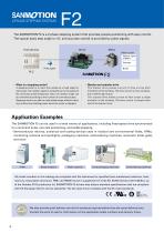
The SANMOTION F2 is a 2-phase stepping system thatthat provides precise positioning with easy control. SANMOTION F2 a 2-phase stepping system provides precise positioning with easy control. The typical step angle is 1.8 , and accurate control is provided by pulse signals. , The typical basicbasic step angle is 1.8°and accurate controlis provided by pulse signals. Host devices Motor Motor option Various types of gears Encoder Pulse signal ・ What is a stepping motor? ・ Bipolar and unipolar drive A stepping motor is a motor that rotates at a fixed angle for each pulse. The rotation speed is proportional...
Open the catalog to page 4
Lineup Set Models ▶p. 9– AC input Bipolar The AC power supply input driver comes as a set model with the motor. A wide range of input voltages can be handled, from 100 to 240 VAC*. The motor winding is bipolar. *The 42 mm sq. (1.65 inch sq.) motor model only supports 100 to 120 VAC. Motor size: 42 mm sq. (1.65 inch sq.)/60 mm sq. (2.36 inch sq.)/86 mm sq. (3.39 inch sq.) Unipolar These set models consist of a DC-powered driver and motor. The input voltage range is from 24 to 36 VDC, and the motor winding is unipolar. Motor size: 28 mm sq. (1.10 inch sq.)/42 mm sq. (1.65 inch sq.)/56 mm sq. (2.20...
Open the catalog to page 5
Lineup Details Number of divisions 1-256 (16 levels) 1,2,4,8,16 1,2,4,8,16 *The 42 mm sq. (1.65 inch sq.) motor model (AC input set model) only supports 100 to 120 VAC input. Driver, Motor,
Open the catalog to page 6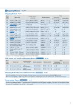
Stepping Motors ▶p. 49– Stepping Motors ▶p. 54– Basic step angle Holding torque N·m (oz·in) Motor size Model number Specifications/ Characteristics diagram Contact us for available encoders, gears and motors with brakes. IP65 Splash and Dust Proof Stepping Motors Waterproof, dustproof ▶p. 89– Page Basic step angle Motor size CE/UL Model CE/UL Model Holding torque N·m (oz·in) Safety standards Model number Specifications/ Dimensions Characteristics diagram Stepping Motors for Vacuum Environments Customized Products ▶p. 95 We can customize motors for use in low to ultra-high vacuum environments...
Open the catalog to page 7
T his dr i ver f e a t ur e s ap pr ox ima te l y 10 % le s s vibration compared with our conventional product (when used with an AC input driver). Also, a low-vibration mode func tion provides smooth driving, even with one-division (full-step) and t wo - division (half-step) coarse resolution settings. This allows vibrations to be suppressed without control system restrictions. Settings possible with setup software Se tup s of t war e c an b e us e d w ith a p er s onal computer to adjust control parameters, or to analyze alarms and operation status. Speed variation (%) Parameter setting screen...
Open the catalog to page 10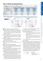
AC Input Set Models/ Drivers Unipolar Models Specifications 28 mm sq. (1.10 in sq.)/Basic step angle 1.8° Motor size Motor length Single Set model number shaft Configuration item: motor number Set model number Dual shaft Configuration item: motor number Holding torque N·m (oz·in) Rotor inertia × 10 -4kg·m2 (oz·in2) Rated current A/phase Motor mass *1 kg (lbs) Allowable thrust load N (lbf) Allowable radial load *2 N (lbf) *1 Driver mass▶p. 45 *2 The load point is at the tip of the output shaft. Full step Half step Source current Full step Half step Half step the stepping motor included in the100...
Open the catalog to page 11
AC Input Set Models Bipolar Set Model Configuration p. 14 Specifications/Characteristics Diagram pp. 16 to 19 Motor Dimensions p. 20 Motor Specifications p. 21 Driver Dimensions p. 22 Driver Specifications p. 22 Driver Model number: F2BAW200M100 Motor rated current: 2 A Model number: F2BAW400M100 Motor rated current: 4 A The operation manual can be downloaded from our website. Drivers are available for separate purchase. Connector Power supply and motor connector set Model number: FA-002 Cable Model number for I/O (for connecting host devices) (CN3): FC5S0010A Cable length 1 m (39.4 inch) Motor...
Open the catalog to page 12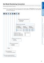
AC Input Set Models/ Drivers Set Model Numbering Convention Not every combination of the following codes or characters is available. Check the set model component details on the following page for the model number combinations, or contact us. DC Input Set Models/ Drivers Example: This is a set model number for the AC input driver (model number: F2BAW200M100) and motor (model number: SH2861-4041). The motor specifications are motor size: 86 mm sq. (3.39 inch sq.), motor length: 66 mm (2.6 inch), single shaft. Stepping Motors Stepping motor shaft specification S: Single shaft D: Dual shaft IP65...
Open the catalog to page 13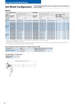
This set includes the driver, motor, power supply and motor connector set, and an I/O cable. Bipolar Single shaft Dual shaft Set configuration items Motor size (Connectors and cables are listed below the table) (Connectors and cables are listed below the table) Basic Rated Page step current angle (A/phase) Specifi- Dimencations sions Motors with brakes, encoders, or with both brakes and encoders are available as options. Contact us for details. Encoders specs are 4000 P/R and 3 channels. 42 mm sq. (1.65 inch sq.) and 60 mm sq. (2.36 inch sq.) motors include lead wires. 86 mm sq. (3.39 inch sq.)...
Open the catalog to page 14
AC Input Set Models/ Drivers Options (sold separately) Power supply and motor connector set Model number: FA-002 PHOENIX CONTACT Name Connector Connector Manufacturer model number Quantity MSTBT 2,5/4-STF-5,08 1 MSTBT 2,5/8-STF-5,08 1 DC Input Set Models/ Drivers Encoder extension connector set Model number: FC5E0000A Manufacturer Tyco Electronics Japan G.K. Name Housing Terminal Housing Terminal Encoder extension cable Housing: 1-1903130-6 Terminal: 1903111-2 Manufacturer: Tyco Electronics Japan G.K. Lead wire: AWG28 Stepping Motors Motor side connector Cable length (L) 1 m (39.4 in) 2 m (78.7...
Open the catalog to page 15All SANYO DENKI EUROPE catalogs and technical brochures
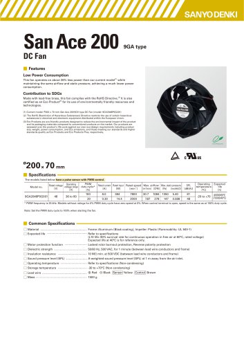 San_Ace_200_9GA_φ200x70
4 Pages
 SAN_ACE_120AD_120x25_ACDC
4 Pages
 San_Ace_40LG_40x28_Long_Life
4 Pages
 STEPPING MOTOR WITH ENCODER
32 Pages
 Company Profile 2023
8 Pages
 SANMOTION G
80 Pages
 San_Ace_140x38_9RA
4 Pages
 San_Ace_160ADW51
4 Pages
 San_Ace_160ADA51
4 Pages
 San_Ace_120ADAW38
4 Pages
 San_Ace_120ADA38
4 Pages
 San Ace 80x38 - 9RA
4 Pages
 San Ace 2022
632 Pages
 SANMOTION F2
84 Pages
 PRODUCT INFORMATION
52 Pages
 San Ace 100W
4 Pages
 San Ace 172AD
4 Pages
 San Ace 120 - 9RA
4 Pages
 San Ace 92 - 9RA
4 Pages
 San Ace 80 - 9RA
4 Pages
 San Ace 60 - 9RA
4 Pages
 San Ace 133W
4 Pages
 SANMOTION_R_3E_AC400V_550W-55kW
128 Pages
 SANMOTION K
28 Pages
 SANMOTION C _ SMC100 _ECAT
12 Pages
 SANMOTION F5
128 Pages
 SANMOTION R
4 Pages
 San Ace Controller
4 Pages
 San Ace 97W
4 Pages
 SANMOTION R 100/200V General Catalog
172 Pages
 SANMOTION_R_AD_48VDC_20-200W
36 Pages
 Model No. PB
104 Pages
 SANMOTION_Linear
4 Pages
 SANMOTION_C_EtherCAT
16 Pages
 SERVOMOTOR_R2_14mm_2W
2 Pages
 DC SERVO SYSTEMS
36 Pages
 3 PHASE STEPPER - SANMOTION F3
12 Pages
 SANUPS HYBRID UPS E11A
8 Pages
 A11J
A11J12 Pages


Archived catalogs
 SANMOTION_C
12 Pages
 San Ace 150W
4 Pages
 San Ace 2018 ver. 2
576 Pages
 5-phase stepping MOTOR
128 Pages
 SERVOMOTOR_R2_275mm_37kW
2 Pages
 SANMOTION_R_100-200V_30W-1kW
40 Pages
 SANMOTION_R_3E_AD_100-200V_30W-30kW
160 Pages


- Electromotor
- DC electromotor
- Multipole motor
- 24 V motor
- Propeller fan
- Servo-motor
- 2-pole motor
- High-efficiency electromotor
- Servo-amplifier
- Stepper motor
- High-performance servo motor
- Motor controller
- AC servo-motor
- High-torque motor
- 48 V motor
- Custom motor
- DC servo-amplifier
- On-line UPS
- Cooling fan
- Fieldbus servo-drive