- Catalogs
- SANYO DENKI America
- SANMOTION MODEL No.PB Ethercat Interface
SANMOTION MODEL No.PB Ethercat Interface
1 /20Pages

SANMOTION MODEL No.PB Ethercat Interface
1 /20Pages
Catalog excerpts
CLOSED LOOP STEPPING SYSTEMS Model No.PB With EtherCAT interface
Open the catalog to page 1
CLOSED LOOP STEPPING SYSTEMS Model No.PB Power voltage Dual axis driver with EtherCAT interface ^ Model Standard Model • Spur Gear Model • Low-backlash Gear Model Harmonic Gear Model • Electromagnetic Brake Model
Open the catalog to page 2
High-Speed Field-Bus EtherCAT Interface EtherCAT is a field-bus system that allows 100Mbps high-speed and highly reliable communication. With this interface, response speed is boosted up, and takt time is greatly reduced. Space-Saving Now one driver can control 2 motors, installation space will be reduced by 30% when compared to the case with controlling by our 2 conventional drivers*. *SANMOTION Model No.PB DC power input type (Model No. PB3D003M20 ) Also Ideally Suited for Equipment Requiring Synchronizing Operation The driver can perform dual-axis synchronizing operation. (While in profile...
Open the catalog to page 3
List of Driver/Motor Combinations and Option Interface type Encoder type Absolute encoder (17bit + multiple rotation 16bit) Spur gear Electromagnetic brake 1/7.2 Low-backlash gear Motor Low-backlash gear 1/30 Harmonic gear Electromagnetic brake Power cable Motor ext. cable Regenerative resistor Motor Standard Specifications Motor type Insulation class Withstand voltage Insulation resistance Vibration resistance 147m/s2 (10 to 70Hz: amplitude 1.52mm, 70 to 2000Hz: 147m/s2 of acceleration) The x, y, and z are each tested 12 times with a sweep time of 15 minutes/cycle. Impact resistance 294m/s2...
Open the catalog to page 4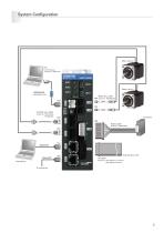
System Configuration Motor ext. cable CN5 Model No.: PBC8M0030A CN8 CN4 Encoder ext. cable Model No.: PBC7E0030A PBC8E0030A Power cable Model No.: PBC9P0020A I/O cable Model No.: PBC1S0010A (un shielded) PBC1S0010C (shielded) Host device
Open the catalog to page 5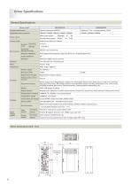
Driver Specifications General Specifications Driver model Encoder specification Applicable motor model No. PBM282, PBM284, PBM423, PBM603, PBM604 Main power supply Control power supply Power source Control mode Absolute (17 bit + multiple rotation 16 bit) PWM control SIN drive method Ambient temp. Vibration resistance 0.5G (tested with frequency range 10 to 55 Hz, X, Y, Z each direction 2H) Impact resistance Operating/ Storage humidity Maximum 2000m above sea level Tray structure rear mounting type Rotation speed Resolution (P/R) Regeneration Process Regenerative resistor (Option) Holding brake...
Open the catalog to page 6
External Wiring Diagram Driver Model No.: PB4D003E2D0 Driver PB4D003E2D0 User unit CN6 Main power supply DC24/48V Control power supply DC24V FG Axis 1 Touch probe input Axis 2 Touch probe input Axis 1 Positive direction limit input Axis 2 Positive direction limit input Holding brake Axis 1 Home input Axis 1 Negative direction limit input Optical incremental encorder Axis 2 Negative direction limit input Axis 2 Home input General-purpose output 1 General-purpose output 2 Twisted pair cable with external shield Driver Model No.: PB4D003EAD0 Driver User unit CN6 Main power supply DC24/48V Control...
Open the catalog to page 7
General Specifications Driver + Standard Model Motor flange size 28mm sq., 42mm sq., 60mm sq. Motor flange size Motor model (Incremental encoder) Motor length Motor mass Related driver model no. Motor model (Absolute encoder) Motor length Motor mass Related driver model no. Max. stall torque Rotor inertia Allowable thrust load Allowable radial load Note 1 Motor characteristics chart Motor Characteristics Chart Maintain motor case temperature at a point below 85°C. Note1: The load point is determined at a position 14mm from the mounting surface. Power consumption
Open the catalog to page 8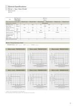
General Specifications Driver + Spur Gear Model Motor flange size 28mm sq. Motor flange size Size Motor length + Gear length Motor model (Incremental encoder) Related driver model No. Allowable torque Rotor inertia Reduction gear ratio Allowable rotations Rotation direction Allowable thrust load Allowable radial load Note1 Motor mass Motor characteristics chart Motor Characteristics Chart Allowable torque Torque (kgf·cm) Maintain motor case temperature at a point below 85°C. Note1: The load point is determined at a position 1/3 of the length from the output shaft.
Open the catalog to page 9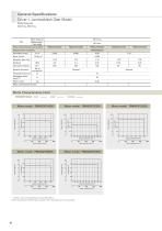
General Specifications Driver + Low-backlash Gear Model Motor flange size 42mm sq., 60mm sq. Motor flange size Size Motor length + Gear length Motor model (Incremental encoder) Related driver model No. Allowable torque Rotor inertia Reduction gear ratio Allowable rotations Rotation direction Allowable thrust load Allowable radial load Note1 Motor mass Motor characteristics chart Motor Characteristics Chart Allowable torque Torque (kgf·cm) Torque (kgf·cm) Maintain motor case temperature at a point below 85°C. Note1: The load point is determined at a position 1/3 of the length from the output shaft....
Open the catalog to page 10
Motor flange size Size Motor length + Gear length Motor model (Incremental encoder) Related driver model No. Allowable torque Allowable rotations Rotation direction Reduction gear ratio Backlash Rotor inertia Allowable thrust load Allowable radial load Note1 Motor mass Motor characteristics chart Torque (kgf·cm) Torque (kgf·cm) Torque (kgf·cm) Torque (kgf·cm) Torque (kgf·cm)
Open the catalog to page 11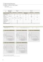
General Specifications Driver + Harmonic Gear Model Motor flange size 28mm sq., 42mm sq., 60mm sq. Motor flange size Size Motor length + Gear length Motor model (Incremental encoder) Related driver model No. Allowable torque Allow. instantaneous torque Rotor inertia Reduction gear ratio Lost motion Hysteresis loss Allowable rotations Allowable thrust load Allowable radial load Note1 Motor mass Motor characteristics chart Motor Characteristics Chart Allowable torque Maintain motor case temperature at a point below 85°C. The gear output shaft rotates in the opposite direction. Note1: The load point...
Open the catalog to page 12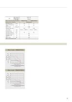
Motor flange size Size Motor length + Gear length Motor model (Incremental encoder) Related driver model No. Allowable torque Allow. instantaneous torque Rotor inertia Reduction gear ratio Lost motion Hysteresis loss Allowable rotations Allowable thrust load Allowable radial load Note1 Motor mass Motor characteristics chart Torque (kgf·cm) Torque (kgf·cm)
Open the catalog to page 13All SANYO DENKI America catalogs and technical brochures
 SANMOTION C S200
16 Pages
 SANUPS A11N-Li
16 Pages
 SANMOTION G
104 Pages
 SANMOTION R
196 Pages
 San Ace Cooling Systems
52 Pages
 San Ace 40L
4 Pages
 San Ace 120AD 9AD type
4 Pages
 San Ace 92 9RA type
4 Pages
 San Ace 92 9GA
5 Pages
 San Ace 140W 9WL
5 Pages
 San Ace 140L 9LG
5 Pages
 San Ace B97 9BMC
2 Pages
 SANMOTION R 3E
172 Pages
 SANMOTION T
36 Pages
 SANMOTION F5
128 Pages
 SANMOTION F2
84 Pages
 SANMOTION C
12 Pages
 DC Fan Catalog
247 Pages
 San Ace 92W
4 Pages
 San Ace B97
2 Pages
 San Ace 172 GP
4 Pages
 San Ace 40
2 Pages
 San Ace 60T
2 Pages
 Blower
20 Pages
 PWM Controller
4 Pages
 SANMOTION MODEL No.PB
2 Pages
 ACDC Fan
5 Pages
 AC San Ace Catalog
56 Pages
 SANMOTION R
40 Pages
 SANMOTION R 400V
36 Pages
 SANMOTION R Medium Capacity
40 Pages
 SANMOTION R ADVANCED MODEL
64 Pages


Archived catalogs
 DC San Ace Catalog
378 Pages
 San Ace Cooling Fan
673 Pages
 San Ace General Catalog
670 Pages
 Electrolytic Corrosion Proof Fan
11 Pages
 Long Life Fan Catalog
91 Pages
 Oil Proof Fan Catalog
126 Pages
 Reversible Flow Fan
4 Pages
 San Ace 92W 9WL
3 Pages
 1 to 5kVA Modular UPS: ASE-H
6 Pages
 1 to 20kVA Modular UPS: A11J
12 Pages
 Splash Proof Fan Catalog
126 Pages
 Online UPS: A11H
4 Pages
 Hybrid UPS
8 Pages
 DC_San_Ace
332 Pages
 AC_San_Ace
56 Pages
 PD-D11A
8 Pages


- Servo-motor
- LIMING air blower
- LIMING single-stage blower
- LIMING centrifugal blower
- High-performance servo motor
- AC servo-motor
- Ultra-compact servomotor
- Robotic servo-motor
- Linear motor
- Servomotor for industrial applications
- High-torque servomotor
- Single-phase blower
- High-speed servomotor
- High-precision servomotor
- Cooling blower
- Electronic fan
- EtherCAT positioning controller
- High-speed linear motor
- Compact motion control card
- Axial electronic fan