- Catalogs
- SANYO DENKI America
- Reversible Flow Fan
Reversible Flow Fan
1 /4Pages

Reversible Flow Fan
1 /4Pages
Catalog excerpts

Reversible Flow Fan ■ Features Reduces the required number of fans ・Multiple fans are usually needed to blow air in both directions to ventilate houses, beverage vending machines, food display cases, and printers. ・Wind direction of the fan can be switched so fewer fans are required. ・Reduces equipment costs and saves space. ・Rotational speed is controlled using an external PWM signal to deliver an appropriate rotational speed, reducing noise and saving energy. Same cooling performance in both directions ・Has approximately the same airflow and static pressure in both blowing directions, so it is easy to control performance. ■ Specifications The following nos. have PWM controls and pulse sensors. Model no. Operating Expected Operating PWM Rated current Rated input Rated speed Max. airflow Max. static pressure SPL Rotation Rated voltage temperature life voltage range duty cycle [A] [W] [min-1] [m3/min] [CFM] [Pa] [inchH2O] [dB(A)] direction [V] (Note) [℃] [h] [V] [%] Forward Reverse Forward Reverse Note: PWM frequency: 25 kHz Available options: Without Sensor Please inquire as the availability of these options depends on the model. ⇒ Lock sensor ■ Common Specifications □ Material ・・・・・・・・・・・・・・・・・・・・・・・・・・ Frame, Impeller: Plastics (Flammability: UL94V-0) □ Expected life ・・・・・・・・・・・・・・・・・・・・・ Refer to specifications (L10: Survival rate: 90% at 60℃, rated voltage, and continuously run in a free air state) □ Motor protection system ・・・・・・・・・・ Current blocking function and reverse polarity protection □ Dielectric strength ・・・・・・・・・・・・・・・・ 50 / 60 Hz, 500 VAC, 1 minute (between lead conductor and frame) □ Sound pressure level (SPL) ・・・・・・・・ Expressed as the value at 1 m from air inlet side □ Operating temperature ・・・・・・・・・・・・ Refer
Open the catalog to page 1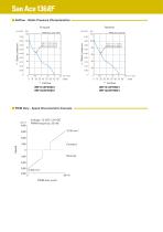
■ Airflow - Static Pressure Characteristics Forward (inch H2O) ■ PWM Duty - Speed Characteristics Example
Open the catalog to page 2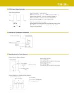
■ PWM Input Signal Example Input signal waveform VIH=4.75 V to 5.25 V VIL=0 V to 0.4 V 1 T1 PWM duty cycle (%) = PWM frequency 25 (kHz) = ×100 Source current (Isource) : 1 mA max. at control voltage 0 V Sink current (Isink) : 1 mA max. at control voltage 5.25 V Control terminal voltage: 5.25 V max. (Open circuit) When the control lead wire is open, the fan speed is the same as the one at a PWM duty cycle of 100%. Either TTL input, open collector or open drain can be used for PWM control input signal. ■ Example of Connection Schematic + ○ Control PWM input signal Isource ■ Specifications for...
Open the catalog to page 3
■ Dimensions (unit: mm) 4-φ3.5±0.3 Mounting Hole (10) Airflow direction (Forward) Airflow direction (Reverse) Rotating direction (Forward) Rotating direction (Reverse) ■ Reference Dimension of Mounting Holes and Vent Opening (unit: mm) Impeller side, Nameplate side 45° ■ Option (unit: mm) Finger guard Model: 109-1139 Surface treatment: Nickel-chrome plating (Color: silver) Impeller side, Nameplate side φ1.6 ●Please read the "Safety Precautions" on our website before using the product. ●The products shown in this catalog are subject to Japanese Export Control Law. Diversion contrary to the law of...
Open the catalog to page 4All SANYO DENKI America catalogs and technical brochures
 SANMOTION C S200
16 Pages
 SANUPS A11N-Li
16 Pages
 SANMOTION G
104 Pages
 SANMOTION R
196 Pages
 San Ace Cooling Systems
52 Pages
 San Ace 40L
4 Pages
 San Ace 120AD 9AD type
4 Pages
 San Ace 92 9RA type
4 Pages
 San Ace 92 9GA
5 Pages
 San Ace 140W 9WL
5 Pages
 San Ace 140L 9LG
5 Pages
 San Ace B97 9BMC
2 Pages
 SANMOTION R 3E
172 Pages
 SANMOTION T
36 Pages
 SANMOTION F5
128 Pages
 SANMOTION F2
84 Pages
 SANMOTION C
12 Pages
 DC Fan Catalog
247 Pages
 San Ace 92W
4 Pages
 San Ace B97
2 Pages
 San Ace 172 GP
4 Pages
 San Ace 40
2 Pages
 San Ace 60T
2 Pages
 Blower
20 Pages
 PWM Controller
4 Pages
 SANMOTION MODEL No.PB
2 Pages
 ACDC Fan
5 Pages
 AC San Ace Catalog
56 Pages
 SANMOTION R
40 Pages
 SANMOTION R 400V
36 Pages
 SANMOTION R Medium Capacity
40 Pages
 SANMOTION R ADVANCED MODEL
64 Pages


Archived catalogs
 DC San Ace Catalog
378 Pages
 San Ace Cooling Fan
673 Pages
 San Ace General Catalog
670 Pages
 Electrolytic Corrosion Proof Fan
11 Pages
 Long Life Fan Catalog
91 Pages
 Oil Proof Fan Catalog
126 Pages
 San Ace 92W 9WL
3 Pages
 1 to 5kVA Modular UPS: ASE-H
6 Pages
 1 to 20kVA Modular UPS: A11J
12 Pages
 Splash Proof Fan Catalog
126 Pages
 Online UPS: A11H
4 Pages
 Hybrid UPS
8 Pages
 DC_San_Ace
332 Pages
 AC_San_Ace
56 Pages
 PD-D11A
8 Pages


- Servo-motor
- LIMING air blower
- LIMING single-stage blower
- LIMING centrifugal blower
- High-performance servo motor
- AC servo-motor
- Ultra-compact servomotor
- Robotic servo-motor
- Linear motor
- Servomotor for industrial applications
- High-torque servomotor
- Single-phase blower
- High-speed servomotor
- High-precision servomotor
- Cooling blower
- Electronic fan
- EtherCAT positioning controller
- High-speed linear motor
- Compact motion control card
- Axial electronic fan