
- Catalogs
- Santroll Electric
- Inverter


Inverter
Inverter
Catalog excerpts
Tianjin Santroll Electric Automobile Technology Co., Ltd. Address: No. 1 Xishi Road, Airport Economic Zone, Tianjin
Open the catalog to page 1
4.1.1 Relevant parameters of motor and position sensor (take resolver as an
Open the catalog to page 2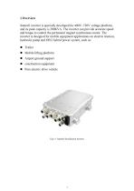
Santroll inverter is specially developed for 400V~720V voltage platform, and its peak capacity is 200KVA. The inverter can provide accurate speed and torque to control the permanent magnet synchronous motor. The inverter is designed for mobile equipment applications on electric traction, hydraulic pump and OEG hybrid power system, such as: • Mobile lifting platform • Airport ground support • construction equipment • Pure electric drive vehicle
Open the catalog to page 4
Sweep frequency vibration
Open the catalog to page 6
1.1 Product function definition • Control function: according to the control requirements of the whole vehicle, the motor inverter receives the signal output by the whole vehicle inverter and controls the running state of the driving motor. The control mode is torque or speed control, and the specific control mode is switched according to the running state of the whole vehicle. • Feedback braking function: the motor inverter has feedback braking management ability, and controls the motor to brake according to the feedback braking request sent by the vehicle inverter and recovers the energy fed...
Open the catalog to page 7
This chapter describes how to install and connect the inverter. This chapter also describes the characteristics and basic configuration of input, output and drivers. The following list describes installation considerations: • Do not install the inverter where unauthorized personnel can reach it; Such as outside the device. • Do not install the inverter in a place where it is easy to be damaged or hit. • Although the inverter provides IP67 entrance protection, please avoid installing the inverter in a position where it may be submerged in water or exposed to high-pressure water for a long time....
Open the catalog to page 8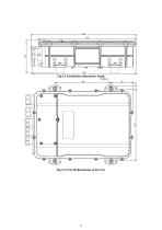
Fig.2-1 Installation dimension: depth Fig.2-2 Overall dimensions of inverter
Open the catalog to page 9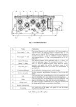
Table 2-2 Connection Description
Open the catalog to page 10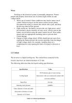
Working on the electrical system is potentially dangerous. Protect people and property from motor out of control, high current arc and voltage shock: • Motor out of control: Some conditions may lead to motor out of control. Before trying to use the motor control circuit, please disconnect the motor or connect the vehicle with a jack, and keep the driving wheel off the ground. • High current arc: the battery can provide very high power, and if the terminal is short-circuited, arc may occur. Always turn on the battery circuit before using the motor control circuit. Wear safety glasses and use appropriate...
Open the catalog to page 11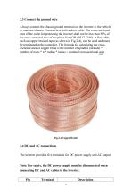
2.3 Connect the ground wire Always connect the chassis ground terminal on the inverter to the vehicle or machine chassis. Connect here with a short cable. The cross-sectional area of the cable for protecting the inverter shall not be less than 50% of the cross-sectional area of the phase line (GB 50217-2018). A flat cable, such as copper braided tape (as shown in Fig.2-4), can be used and must be terminated at the controller. The formula for calculating the crosssectional area of copper braid is the number of spindles (strands) * number of roots * π * radius * radius = nominal cross-sectional...
Open the catalog to page 12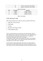
When determining the power cable size, please consider the following: • Apply duty cycle and current • Cable length • Maximum rated voltage of cable • Cable temperature grade The AC cable shield must be connected to the motor housing. The DC cable shield must be connected to the battery case or DC distribution unit. For connection, bolt connection can be used. Do not use pigtails to connect the cable screen to the chassis or housing. A maximum of 70mm2 cable can be used for DC cables. The maximum AC cable is 50mm2 cable. Use five M8*20 hexagon socket head screws with grade 8.8 to fix DC and AC...
Open the catalog to page 13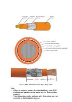
Copper conductor Silicon rubber insulation Tin-plating weaving shield Composite aluminium-plastic tape shield Silicon rubber sheath Fig.2-5 Cutting Dimensions Used for High Voltage Cables Note: Failure to properly connect the cable shield may cause EMC problems and may prevent the motor inverter from working properly. These dimensions are for guidance only. Dimensions may vary according to the installation process. 1
Open the catalog to page 14
2.6 Isolation The inverter provides insulation between high-voltage and low-voltage circuits, and basic insulation between high-voltage circuits and chassis or housing. Low-voltage logic circuits can usually work at the nominal voltage of 9.6V~32V, and high-voltage power stage (B+/B-) can work at the nominal voltage of 400VDC~720VDC. The inverter cannot be directly connected to the AC power grid. As a typical electric vehicle, the high-voltage battery and inverter must be isolated from the AC power supply. Note: DC bus precharge and reverse polarity protection must be provided outside the inverter....
Open the catalog to page 15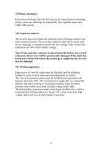
2.9 Passive discharge If the active discharge fails, the inverter has an internal passive discharge circuit, which can discharge the internal DC link capacitor below 60V within 200 seconds. 2.10 Contactor control The inverter does not include the functions of pre-charging contactor and main contactor control. The main line contactor shall not be closed until the pre-charging is completed and the DC bus voltage of the inverter has reached at least 90% of the battery voltage. Note: If the main line contactor is closed when the battery is reversely connected, the inverter will be permanently damaged....
Open the catalog to page 16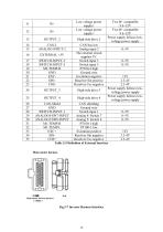
Table 2-5 Definition of External Interface Fig.2-7 Inverter Harness Interface
Open the catalog to page 18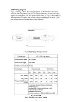
Fig.2-7 and Fig.2-8 are the wiring diagrams of the inverter. The motor position and temperature sensors are connected to the inverter and other inputs are configured as CAN inputs. Please refer to Fig.2-8 for details of the acquisition of analog and switch values owned by the inverter. CAN bus connection conforms to ISO 11898 standard. Fig.2-10 Inverter Low Voltage Wiring
Open the catalog to page 19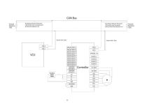
The distance between [the branch Resistance CAN and the main connected point) CAN Bus The distance between (the branch Terminal CAN and the main connected point) and terminal resistance’ ten Controller MI-TEMP
Open the catalog to page 20All Santroll Electric catalogs and technical brochures
 Standard Motor OD 290mm
61 Pages
 Standard Motor OD 220mm
150 Pages
 Standard Motor OD 155mm
198 Pages
 Standard Motor OD 122mm
21 Pages
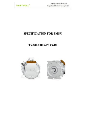 TZ200XB08-T145-DL
4 Pages
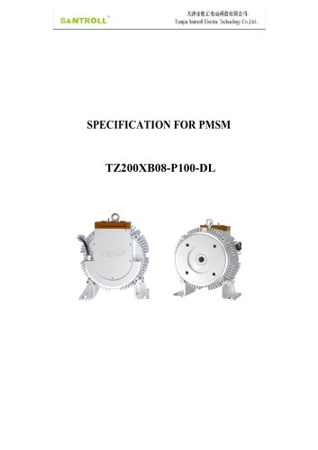 TZ200XB08-P100-DL
4 Pages
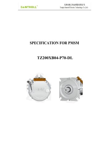 TZ200XB04-T70-DL
4 Pages
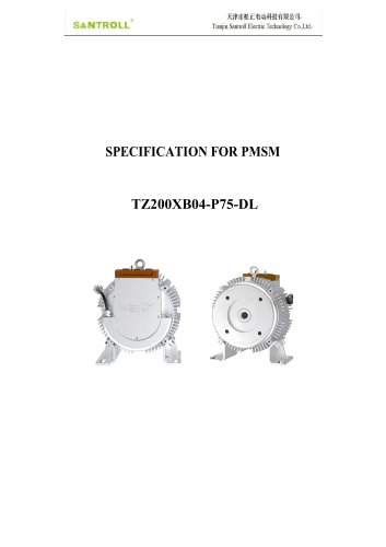 TZ200XB04-P75-DL
4 Pages
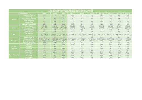 UAV-1
UAV-11 Page
- Electromotor
- Alternating current motor
- Electromotor for industrial applications
- Three-phase motor
- Compact electromotor
- High-efficiency electromotor
- Pump motor
- Permanent magnet motor
- 380 V motor
- Motor controller
- High-torque motor
- Custom motor
- Medical equipment motor
- Small motor
- Aluminium motor
- IP65 motor
- High-speed motor
- High-power motor
- Conveyor motor