Catalog excerpts
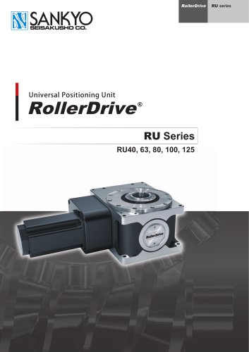
Universal Positioning Unit
Open the catalog to page 1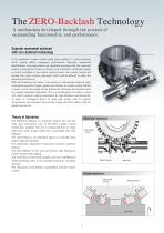
A mechanism developed through the pursuit of outstanding functionality and performance. Superior movement achieved with zero-backlash technology In FA equipment, motion control using servo systems is a crucial element which greatly affects equipment performance. Naturally, equipment specifications and performance are designed assuming that the expected motion is attained, but if there are factors such as backlash, insufficient rigidity or control instability in the motion control section, then output motion will deviate from input control commands, and it will be difficult to attain the...
Open the catalog to page 2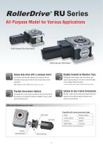
All-Purpose Model for Various Applications RU40 Standard Gear Ratio Model RU80 High Gear Ratio Model Heavy-duty drive with a compact motor Rigidity Suitable for Machine Tools Our product lineup includes high gear ratio reducers that use Redesigned internal design, cast iron housing, rigid proprietary reducer gears to deliver heavy torque using a small output. Uses bearings for more than 5 times the rigidity of our existing models (RA series). Gear ratios are 1/20, 1/60 (RU40 comes with 1/15 or 1/45) For use on machine tools, select the waterproof and dust-proof option. Flexible Servomotor...
Open the catalog to page 3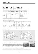
Model Code Model Code Figure A. Oil lubrication mounting position code Figure B. RollerDrive Surfaces Standard gear ratio model Motor bracket RollerDrive body Notes on Water-proof, Dust-proof Products Water-proofing and dust-proofing are provided as options to protect the RU Series. Sankyo performed industrial testing based on IEC60529 for IP66M conditions. There- after, TUV Rheinland Japan confirmed that the RU Series chassis was free of water [Testing was done on the RU80 (reduction ratio 20).] RollerDrive body ij) Shown with servomotor on 'T surface P is an abbreviation for International...
Open the catalog to page 5
RollerDrive Specifications The RU series has two different lubrication options. Select the lubrication type according to your operating conditions. Grease lubrication is the standard lubrication method, while oil lubrication should be selected for high-speed operation. To check that the service life of the RollerDrive will be satisfactory, please compare the specifications for each lubrication type. On the dynamic rated output torque curve (see page 6), when the point (Torque and Speed) is below the curve, an expected life of over 12,000 hours is ensured. Capacity Table [Grease Lubrication]
Open the catalog to page 6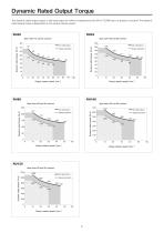
Dynamic Rated Output Torque The dynamic rated output torque is the load torque for which an expected service life of 12,000 hours or greater is ensured. The dynamic rated output torque is dependent on the output rotation speed. Output rotation speed [min-1] Output rotation speed [min-1]
Open the catalog to page 7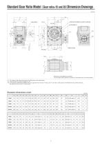
Standard Gear Ratio Model [Gear ratio=l5 and 20)Dimension Drawings Servomotor to be supplied by customer. Use the model code to specify the position of the access hole in the motor bracket. ^1 The number of tap holes can be found in the Dimensions chart shown below. ^2 These dimension are listed on pages 9 to 18. m 6 x M5 and 6 x M6 (RU40 and RU63) holes, the angle with the 5-mm dia. H7 hole is 30°. For 8 x M6, 8 x M8, and 8 x M10 (RU80, RU100, and RU125) holes, the angle with the 5-mm dia. H7 hole is 22.5°. Standard dimensions chart
Open the catalog to page 8
High Gear Ratio Model [Gearratioesand 60)Dimension Drawings Servomotor to be supplied by customer. ^1 The number of tap holes can be found in the dimensions chart shown below. ^2 The motor flange is used with gear box housing when DS, ES, FS servomotor fastener elements is chosen for RU100. ^3 6 x M5 and 6 x M6 (RU40 and RU63) holes, the angle with the 5-mm dia. H7 hole is 30°. For 8 x M6, 8 x M8, and 8 x M10 (RU80, RU100, and RU125) holes, the angle with the 5-mm dia. H7 hole is 22.5°. High gear ratio dimensions chart
Open the catalog to page 9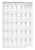
Oil Plug, Oil Level Gauge, Drain Porter on lubricated units) Mounting position i deep, ceunterPere depth 7 5) \ deep, counterPore depth 35) Note 1) If model RU40 is mounted in Note 2) The counterbore depth is the positions 5 or 6, the oil level gauge wil depth from the outermost surface of the be installed on side T or U, whichever side the motor is not mounted on. side on which the oil plug and related parts are mounted.
Open the catalog to page 10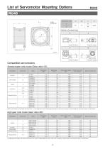
List of Servomotor Mounting Options RU4O On high gear ratio models, the access hole faces the S surface. Please prepare the servo motor with no keyway. Consult Sankyo for using with motors not listed above.
Open the catalog to page 11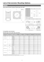
List of Servomotor Mounting Options Motor bracket dimension drawings (Standard gear ratio model) Refer to the position of the access hole for the box □ in the attachment code. Please prepare the servo motor with no keyway. Consult Sankyo for using with motors not listed above.
Open the catalog to page 12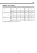
High gear ratio model [Gear ratio=60] On high gear ratio models, the access hole faces the S surface. Please prepare the servo motor with no keyway. Consult Sankyo for using with motors not listed above.
Open the catalog to page 13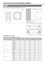
List of Servomotor Mounting Options Motor bracket dimension drawings (Standard gear ratio model) Towa rd R s u rface Towa rd S s u rface Towa rd V s u rface Towa rd W s u rface Compatible servomotors Standard gear ratio model [Gear ratio=20]
Open the catalog to page 14
List of Servomotor Mounting Options Standard gear ratio model [Gear ratio=20] On high gear ratio models, the access hole faces the S surface. Please prepare the servo motor with no keyway. Consult Sankyo for using with motors not listed above.
Open the catalog to page 16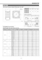
Motor bracket dimension drawings (Standard gear ratio model)
Open the catalog to page 17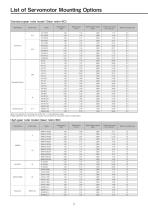
List of Servomotor Mounting Options Standard gear ratio model [Gear ratio=20]
Open the catalog to page 18
On high gear ratio models, the access hole faces the S surface. Please prepare the servo motor with no keyway. Consult Sankyo for using with motors not listed above.
Open the catalog to page 19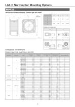
List of Servomotor Mounting Options Motor bracket dimension drawings (Standard gear ratio model)
Open the catalog to page 20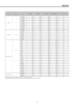
Refer to the position of the access hole for the box □ in the attachment code. Please prepare the servo motor with no keyway. Consult Sankyo for using with motors not listed above.
Open the catalog to page 21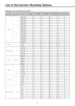
List of Servomotor Mounting Options High gear ratio model [Gear ratio=60]
Open the catalog to page 22All SANKYO catalogs and technical brochures
-
RCC Series
8 Pages
-
RW series
8 Pages
-
SPC Series
2 Pages
-
TCU Series
2 Pages
-
RSD Series
1 Pages
-
EX Series
1 Pages
-
DSS Series
1 Pages
-
DST Series
1 Pages
-
VS-s Series
2 Pages
-
CNC Series
16 Pages
-
ECO Series
32 Pages
-
α (Alpha) Series
44 Pages
-
Large RU Series
24 Pages
-
RU Series
28 Pages
-
RE series
20 Pages
-
Precision adjustable feed Variax
12 Pages
-
SANDEX
8 Pages
-
Do series
7 Pages
-
DT, DTR series
11 Pages
-
RY series
16 Pages
-
RA series
32 Pages

