DT, DTR series
1 /11Pages
DT, DTR series
1 /11Pages
Catalog excerpts

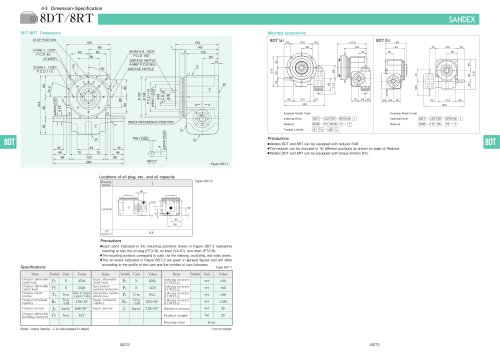
STOP POSITION GREASE NIPPLE GREASE NIPPLE INDEX REFERENCE POSITION, Locations of oil plug, ets., and oil capacity •Each point indicated in the mounting positions shown in Figure 8DT-2 represents (starting at top) the oil plug (PT3/8), oil level (VA-01), and drain (PT3/8). •The mounting positions correspond to code i for the indexing, oscillating, and rotary drives. •The oil levels indicated in Figure 8DT-2 are given in general figures and will differ according to the profile of the cam and the number of cam followers. Note : Input inertia : J is calculated in dwell Mounted accessories Example Model Code Example Model Code •Models 8DT and 8RT can be equipped with reducer R48. •The reducer can be mounted in 16 different positions as shown on page of Reducer. •Models 8DT and 8RT can be equipped with torque limiters 8T0.
Open the catalog to page 1
STOP POSITION GREASE NIPPLE GREASE NIPPLE INDEX REFERENCE POSITION/ Locations of oil plug, ets., and oil capacity •Each point indicated in the mounting positions shown in Figure 11 DT-2 represents (starting at top) the oil plug (PT3/8), oil level (VA-01), and drain (PT3/8). •The mounting positions correspond to code i for the indexing, oscillating, and rotary drives. •The oil levels indicated in Figure 11 DT-2 are given in general figures and will differ according to the profile of the cam and the number of cam followers. Note : Input inertia : J is calculated in dwell Mounted accessories Example...
Open the catalog to page 2
INDEX REFERENCE POSITION
Open the catalog to page 3
STOP POSITION GREASE NIPPLE Locations of oil plug, ets., and oil capacity •Each point indicated in the mounting positions shown in Figure 18DT-2 represents (starting at top) the oil plug (PT1/2), oil level (VA), and drain (PT1/2). •The mounting positions correspond to code i for the indexing, oscillating, and rotary drives. •The oil levels indicated in Figure 18DT-2 are given in general figures and will differ according to the profile of the cam and the number of cam followers. Note : Input inertia : J is calculated in dwell Mounted accessories Example Model Code Torque Limiter Example Model...
Open the catalog to page 4
Locations of oil plug, ets., and oil capacity Note : Input inertia : J is calculated in dwell Mounted accessories Example Model Code Example Model Code Example Model Code Torque Limiter Example Model Code •Models 25DT and 25RT can be equipped with reducers R100 and R125. •The reducer can be mounted in 16 different positions as shown on page of Reducer. •Models 25DT and 25RT can be equipped with torque limiters 25To.
Open the catalog to page 5
Locations of oil plug, ets., and oil capacity Note : Input inertia : J is calculated in dwell Mounted accessories Example Model Code Example Model Code Example Model Code Example Model Code Indexing Drive •Models 35DT and 35RT can be equipped with reducers R125 and R160 •The reducer can be mounted in 16 different positions as shown on page of Reducer,
Open the catalog to page 6
STOP POSITION GREASE NIPPLE Locations of oil plug, ets., and oil capacity Example Model Code Example Model Code Example Model Code Example Model Code •Models 45DT and 45RT can be equipped with reducer R160. •The reducer can be mounted in 16 different positions as shown on page of Reducer.
Open the catalog to page 7
Locations of oil plug, ets., and oil capacity •Each point indicated in the mounting positions shown in Figure 45DTR-2 represents (starting at top) the oil plug (PT1), oil level (VB), and drain (PT1) •The mounting positions correspond to code i for the indexing, oscillating, and rotary drives, •The oil levels indicated in Figure 45DTR-2 are given in general figures and will differ according to the profile of the cam and the number of cam followers. Note : Input inertia : J is calculated in dwell
Open the catalog to page 8
Locations of oil plug, ets., and oil capacity •Each point indicated in the mounting positions shown in Figure 55DTR-2 represents (starting at top) the oil plug (PT2), oil level (VC), and drain (PT1) •The mounting positions correspond to code i for the indexing, oscillating, and rotary drives, •The oil levels indicated in Figure 55DTR-2 are given in general figures and wil differ according to the profile of the cam and the number of cam followers. Note : Input inertia : J is calculated in dwell
Open the catalog to page 9
Locations of oil plug, ets., and oil capacity •Each point indicated in the mounting positions shown in Figure 65DTR-2 represents (starting at top) the oil plug (PT2), oil level (VC), and drain (PT1) •The mounting positions correspond to code i for the indexing, oscillating, and rotary drives, •The oil levels indicated in Figure 65DTR-2 are given in general figures and will differ according to the profile of the cam and the number of cam followers. Note : Input inertia : J is calculated in dwell
Open the catalog to page 10
STOP POSITION Note : Input inertia : J is calculated in dwell
Open the catalog to page 11All SANKYO catalogs and technical brochures
 RCC Series
8 Pages
 RW series
8 Pages
 SPC Series
2 Pages
 TCU Series
2 Pages
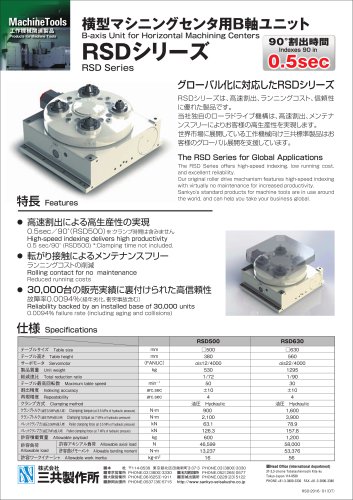 RSD Series
1 Page
 EX Series
1 Page
 DSS Series
1 Page
 DST Series
1 Page
 VS-s Series
2 Pages
 CNC Series
16 Pages
 ECO Series
32 Pages
 α (Alpha) Series
44 Pages
 Large RU Series
24 Pages
 RU Series
28 Pages
 RE series
20 Pages
 Precision adjustable feed Variax
12 Pages
 SANDEX
8 Pages
 RollerDrive
28 Pages
 Do series
7 Pages
 RY series
16 Pages
 RA series
32 Pages


Archived catalogs

- Coaxial gearhead
- Precision gearhead
- Compact gearhead
- Feeder
- Turntable
- Shaft gearhead
- Electric rotary table
- Low-backlash gearhead
- Motor-driven rotary table
- Vibrating feeder
- Index unit
- Vertical rotary table
- Cam indexer
- Rotary indexer
- CNC rotary table
- Mounted gear reducer
- Machine indexer
- Tilting rotary table
- Linear feeder
- Roller feeder