

Do series

Do series
Overview
This document provides comprehensive technical specifications, dimensional data, mounting instructions, and operational parameters for a range of indexing drives (models 25Do, 30Do, 35Do, 45Do, 55Do, 65Do, and 80Do) equipped optionally with spur gear reducers (R48, R65, R80, R100, R125, R160). It serves as a detailed reference for selecting, mounting, and operating these precision indexing drives.
1. General Specifications and Precautions
- Each indexing drive model supports specific reducer types: 25Do and 30Do with R48 and R65; 35Do with R65 and R80; 45Do with R80; 55Do with R80 and R100; 65Do with R100 and R125; 80Do with R125 and R160.
- Reducers can be mounted in up to 16 different positions, requiring careful selection of spacer thickness based on dimension diagrams to ensure proper assembly.
- Standard models ordered with spur gear reducers are considered special specifications and should be confirmed before ordering.
- Oil plug, oil level, and drain locations vary by mounting position and model, with oil capacities specified accordingly.
- Oil levels indicated are general guidelines and must be verified according to actual cam profiles and number of cam followers to maintain proper lubrication.
2. Dimensional Data and Mounting Details
- Detailed dimension figures are provided for each model, including mounting hole locations, bolt sizes, thread pitches, pitch circle diameters (P.C.D.), and surface thicknesses.
- Mounting hole specifications cover index, stationary, and V surfaces with precise measurements to ensure correct installation.
- Mounting positions are illustrated with clear indications of oil plug, oil level, and drain points for proper oil management.
3. Spur Gear Specifications
| Parameter | Symbol | Unit | Typical Values (Example: SG25) |
|---|---|---|---|
| Gear ratio | i | – | 1/2 |
| Large gear torque capacity | TG | N·m | 169.5 (SG25), 201.8 (SG30), 397.9 (SG35), 661.5 (SG45), 721.3 (SG55) |
| Pinion shaft allowable axial load | C2 | N | 1000 (SG25), 1352 (SG30), 1813 (SG35), 2264 (SG45), 2264 (SG55) |
| Pinion shaft maximum repetitious bending force | C3 | N | 980 (SG25), 1235 (SG30), 1813 (SG35), 2185 (SG45), 2185 (SG55) |
| Pinion gear inertia | P7 | kg·m² | 8.5×10⁻⁴ (SG25), 1×10⁻³ (SG30), 2.5×10⁻³ (SG35), 5×10⁻³ (SG45), 7.5×10⁻³ (SG55) |
| Spur gear finishing accuracy | Grade | – | 2 Grade for all models |
Note: Pinion shaft speed should be maintained below 30 rpm to ensure allowable torque and bending force limits are not exceeded.
4. Performance Parameters
- Output allowable axial and radial loads, static torque, torsional rigidity, and bending moments are specified per model.
- Input allowable axial load, maximum repetitious bending force, maximum repetitious allowable torque, and input torsional rigidity are provided.
- Indexing accuracy is detailed for 1 to 4 dwell positions, with typical angular deviations ranging from ±20 to ±120 seconds depending on model and dwell count.
- Product weights increase with model size, ranging from approximately 20-30 kg (smaller models) up to 780 kg (largest models).
- Housing color is consistently gray across all models.
5. Mounting and Oil Management
- Mounting positions correspond to specific codes for indexing, oscillating, and roller drives.
- Oil plug and drain ports use PT1/2 or PT3/4 threads depending on model size.
- Oil capacity varies by model and mounting position, with specific volumes indicated in mounting diagrams.
- Oil level indicators (VA or VA-01) are positioned according to mounting orientation and cam profile to ensure proper lubrication.
6. Model Coding Examples
- Model codes include indexing drive designation, reducer type, and spur gear reducer model (e.g., 1SRG3VW16242R25DO for 25Do with spur gear reducer SG25).
- Reducer codes such as R48, R65, R80, R100, R125, and R160 specify the reducer type used.
7. Critical Notes and Recommendations
- Careful selection of spacer thickness based on dimension diagrams is essential for correct reducer mounting.
- Standard models with spur gear reducers are special order; confirm specifications before procurement.
- Oil levels must be verified according to actual cam profile and follower count to maintain proper lubrication and performance.
- Input inertia (J) is calculated during dwell periods and is critical for dynamic performance assessment.
- Pinion shaft speed should be kept below 30 rpm to avoid exceeding allowable torque and bending force limits.
8. Summary of Critical Parameters for 65Do and 80Do Models
| Parameter | Symbol | Unit | Typical Value (65Do) | Typical Value (80Do) |
|---|---|---|---|---|
| Output Allowable Axial Load | – | N | ~2842 | ~4312 |
| Output Allowable Radial Load | – | N | ~2744 | ~3430 |
| Output Static Torque | Ts | N·m | 1452.4 | 1906.1 |
| Output Torsional Rigidity | K1 | N·m/rad | 2.5×10⁻² | 4×10⁻² |
| Input Allowable Axial Load | – | N | 26460 | 34300 |
| Input Maximum Repetitious Bending Force | – | N | 1666 | 2842 |
| Input Maximum Repetitious Allowable Torque | – | N·m | 3.33×10⁷ | 6.27×10⁷ |
| Indexing Accuracy (1 DWELL) | – | sec | ±20 | ±20 |
| Product Weight | – | kg | 20 | 20 |
Note: Values are approximate and should be confirmed with detailed tables and drawings for design and application.
Conclusion
This document is an essential technical guide for engineers and technicians involved in the selection, installation, and maintenance of indexing drives with spur gear reducers. It ensures optimal performance, reliability, and longevity by providing precise mechanical dimensions, load capacities, inertia values, lubrication guidelines, and critical operational limits.
Catalog excerpts

Locations of oil plug, ets., and oil capacity Dimension of W surface Precautions •Each point indicated in the mounting positions shown in Figure 25Do-3 represents (starting at top) the oil plug (PT112), oil level (VA-01), and drain (PT112). •The mounting positions correspond to code i for the indexing, oscillating, and roller drives, •The oil levels indicated in Figure 25Do-3 are given in general figures and will differ according to the profile of the cam and the number of cam followers.
Open the catalog to page 1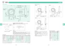
Locations of oil plug, ets., and oil capacity Dimension of W surface Precautions •Each point indicated in the mounting positions shown in Figure 30Do-3 represents (starting at top) the oil plug (PT1/2), oil level (VA), and drain (PT1/2). •The mounting positions correspond to code i for the indexing, oscillating, and roller drives, •The oil levels indicated in Figure 30Do-3 are given in general figures and will differ according to the profile of the cam and the number of cam followers.
Open the catalog to page 2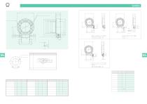
Locations of oil plug, ets., and oil capacity Dimension of W surface Precautions •Each point indicated in the mounting positions shown in Figure 35Do-3 represents (starting at top) the oil plug (PT1/2), oil level (VA), and drain (PT1/2). •The mounting positions correspond to code i for the indexing, oscillating, and roller drives, •The oil levels indicated in Figure 35Do-3 are given in general figures and will differ according to the profile of the cam and the number of cam followers.
Open the catalog to page 3
Locations of oil plug, ets., and oil capacity Mounting hole locations •Each point indicated in the mounting positions shown in Figure 45Do-3 represents (starting at top) the oil plug (PT3/4), oil level (VA), and drain (PT3/4). •The mounting positions correspond to code i for the indexing, oscillating, and roller drives. •The oil levels indicated in Figure 45Do-3 are given in general figures and will differ according to the profile of the cam and the number of cam followers.
Open the catalog to page 4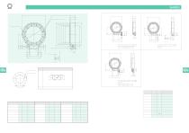
Locations of oil plug, ets., and oil capacity Mounting hole locations •Each point indicated in the mounting positions shown in Figure 55Do-3 represents (starting at top) the oil plug (PT3/4), oil level (VA), and drain (PT3/4). •The mounting positions correspond to code i for the indexing, oscillating, and roller drives, •The oil levels indicated in Figure 55Do-3 are given in general figures and will differ according to the profile of the cam and the number of cam followers.
Open the catalog to page 5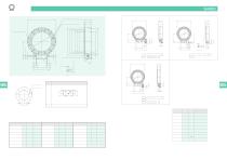
Locations of oil plug, ets., and oil capacity Mounting hole locations •Each point indicated in the mounting positions shown in Figure 65Do-3 represents (starting at top) the oil plug (PT1), oil level (VB), and drain (PT1). •The mounting positions correspond to code i for the indexing, oscillating, and roller drives, •The oil levels indicated in Figure 65Do-3 are given in general figures and will differ according to the profile of the cam and the number of cam followers.
Open the catalog to page 6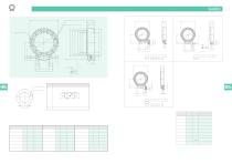
Locations of oil plug, ets., and oil capacity Mounting hole locations •Each point indicated in the mounting positions shown in Figure 80Do-3 represents (starting at top) the oil plug (PT1), oil level (VB), and drain (PT1). •The mounting positions correspond to code i for the indexing, oscillating, and roller drives, •The oil levels indicated in Figure 80Do-3 are given in general figures and will differ according to the profile of the cam and the number of cam followers.
Open the catalog to page 7All SANKYO catalogs and technical brochures
 RCC Series
8 Pages
 RW series
8 Pages
 SPC Series
2 Pages
 TCU Series
2 Pages
 RSD Series
1 Page
 EX Series
1 Page
 DSS Series
1 Page
 DST Series
1 Page
 VS-s Series
2 Pages
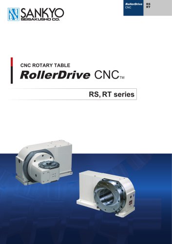 CNC Series
16 Pages
 ECO Series
32 Pages
 α (Alpha) Series
44 Pages
 Large RU Series
24 Pages
 RU Series
28 Pages
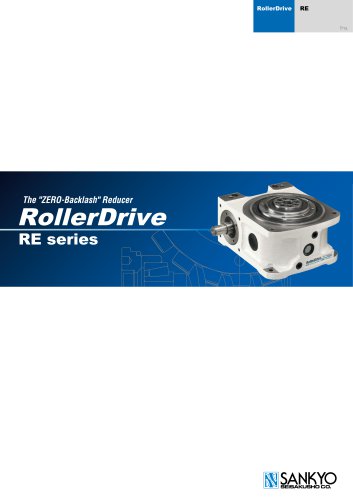 RE series
20 Pages
 Precision adjustable feed Variax
12 Pages
 SANDEX
8 Pages
 RollerDrive
28 Pages
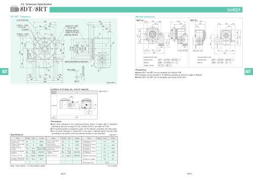 DT, DTR series
11 Pages
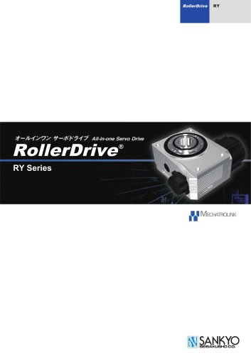 RY series
16 Pages
 RA series
32 Pages


Archived catalogs

- Coaxial gearhead
- Precision gearhead
- Compact gearhead
- Feeder
- Turntable
- Shaft gearhead
- Electric rotary table
- Low-backlash gearhead
- Motor-driven rotary table
- Vibratory feeder
- Index unit
- Vertical rotary table
- Cam indexer
- Rotary indexer
- CNC rotary table
- Mounted gear reducer
- Machine indexer
- Tilting rotary table
- Linear feeder
- Roller feeder