α (Alpha) Series
1 /44Pages

α (Alpha) Series
1 /44Pages
Catalog excerpts

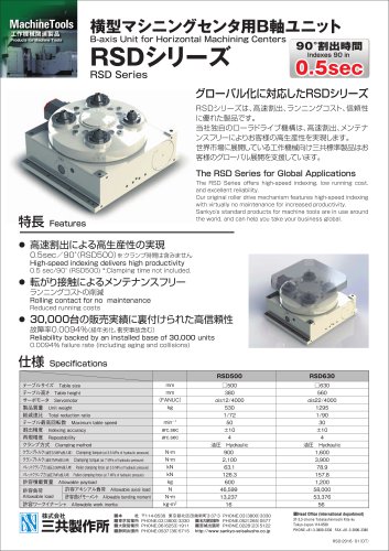
Optimum Reliability in Motion Control Units INDEXING DRIVES
Open the catalog to page 1
As the world's attention shifts toward global environmental issues, companies are placing strong emphasis on internationally recognized guidelines such as ISO14000. The trend is to raise productivity and efficiency without compromising conservation efforts. Sankyo looks at this as an opportunity to build environment-friendly products with sound, perfected, and reliable motion characteristics. Introducing the Sandex a (Alpha) series, a new addition to our Sandex series, which has provided the industry with quality indexing equipment for 25 years. The Sandex a series is a low profile indexing drive...
Open the catalog to page 2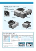
Alpha Series (Standard Type) The number of motor power in ( ) is a special instruction ^Specifications and dimensions are subject to change whithout notice. Always double check before ordering.
Open the catalog to page 3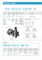
Model Code
Open the catalog to page 4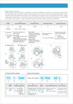
Model Selection information Sandex model codes are specified by a combination of numbers and alphabetic characters. An erroneously specified product code will usually result in a product unusable in other applications. Use the same caution when specifying the product code for the geared motor and optional torque limiters. When specifying other requirements such as special gear ratios, motor voltages, copper plated terminal boxes, etc., include the symbol X at the end of the product code and attach a separate user requirements sheet. Queries concerning price, volume, and delivery should be directed...
Open the catalog to page 5
Note: Input inertia: J is calculated in dwell. 1 N-m=0.102kgf-m
Open the catalog to page 6
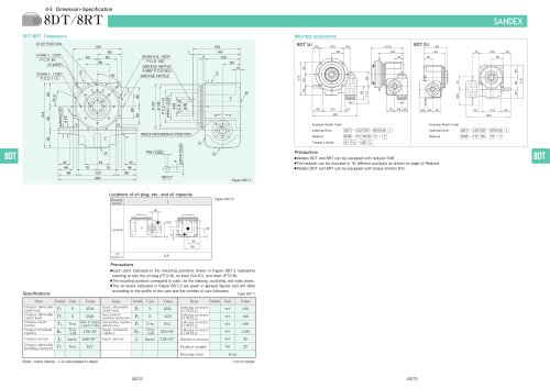
Specifications of geared motor Table 7AD-3 • Each point indicated in the mounting positions shown in Figure 7AD-7 represents (starting at top) the oil plug (PT1/4) , oil level (VA-01) , and drain (PT1/4) . • The mounting positions correspond to code i for the indexing drives. • The oil capacities indicated in Figure 7AD-7 are given in general figures and will differ according to the profile of the cam and the number of cam followers.
Open the catalog to page 7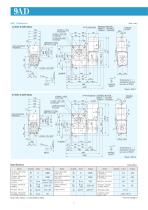
Note: Input inertia: J is calculated in dwell. 1 N-m=0.102kgf-m
Open the catalog to page 8
Specifications of geared motor Table 9AD-3 Torque limiter mounting specifications (option) Timing cam-Photo switch Example Model Code Torque Limiter Sensor Model Connector Model Example Model Code Timing Cam-Photo Switch JQ - •The dimension drawing (Figure 9AD-1, 9AD-2) shows the standard mounting position for the geared motor. •Model 9AD can be equipped with 0.2kW and 0.4kW motor. Note.when using the 0.4kW motor. the motor will protrude beyond the indexer flange. •Model 9AD can be equipped with torque limiter 9TAD •Up to 3 sets of timing cams and photo switches can be added as necessary. •The...
Open the catalog to page 9
Note: Input inertia: J is calculated in dwell. 1 N-m=0.102kgf-m
Open the catalog to page 10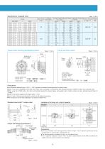
Specifications of geared motor Table 11AD-3 • Each point indicated in the mounting positions shown in Figure 11 AD-7 represents (starting at top) the oil plug (PT1/2) , oil level (VA) , and drain (PT1/2) . • The mounting positions correspond to code i for the indexing drives. • The oil capacities indicated in Figure 11 AD-7 are given in general figures and will differ according to the profile of the cam and the number of cam followers.
Open the catalog to page 11
GEARED MOTOR HANDLE SHAFT Figure 15AD-2 Note: Input inertia: J is calculated in dwell. 1 N-m=0.102kgf-m
Open the catalog to page 12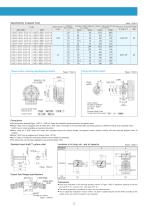
Specifications of geared motor Table 15AD-3 Sensor Model Connector Model Example Model Code Timing Cam-Photo Switch JQ - [T] - 15AD •The dimension drawing(Figure 15AD-1, 1 5AD-2) shows the standard mounting position for geared motor. •Model 15AD can be equipped with 0.75kW and 1.5kW motor. Exchange is not permitted after purchase because of different hollow size of geared motor. 2.2kW motor is also available as special instructions •When using the 1.5kW motor, the motor will protrude beyond the indexer flange, and geared motor's bottom surface will also protrude beyond Index W •Model 15AD can...
Open the catalog to page 13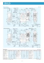
GREASE FITTING INDEX REFERENCE GEARD MOTOR GREASE FITTING GEARD MOTOR Note: Input inertia: J is calculated in dwell. 1 N-m=0.102kgf-m
Open the catalog to page 14
Specifications of geared motor Table 19AD-3 • Each point indicated in the mounting positions shown in Figure 19AD-7 represents (starting at top) the oil plug (PT3/4) , oil level (VB) , and drain (PT3/4) . • The mounting positions correspond to code i for the indexing drives. • The oil capacities indicated in Figure 19AD-7 are given in general figures and will differ according to the profile of the cam and the number of cam followers.
Open the catalog to page 15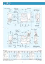
Note: Input inertia: J is calculated in dwell. 1 N-m=0.102kgf-m
Open the catalog to page 16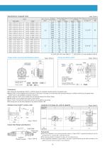
Specifications of geared motor Fixed flange Output shaft Locations of oil plug, etc., and oil capacity • Each point indicated in the mounting positions shown in Figure 23AD-7 represents (starting at top) the oil plug (PT3/4) , oil level (VB) , and drain (PT3/4) . • The mounting positions correspond to code i for the indexing drives. • The oil capacities indicated in Figure 23AD-7 are given in general figures and will differ according to the profile of the cam and the number of cam followers.
Open the catalog to page 17
STOP POSITION GEARD MOTOR STOP POSITION GEARD MOTOR_ represents terminal Note: Input inertia: J is calculated in dwell. 1 N-m=0.102kgf-m
Open the catalog to page 18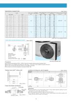
Specifications of geared motor Output shaft Locations of oil plug, etc., and oil capacity • Each point indicated in the mounting positions shown in Figure 33AD-6 represents (starting at top) the oil plug (PT3/4) , oil level (VB) , and drain (PT3/4) . • The mounting positions correspond to code i for the indexing drives. • The oil capacities indicated in Figure 33AD-6 are given in general figures and will differ according to the profile of the cam and the number of cam followers.
Open the catalog to page 19
GREASE FITTING STOP POSITION INDEX REFERENCE (SCRIBED LINE) EXTENSION SHAFT/ GEARD MOTOR SHRINK DISC represents terminal Note: Input inertia: J is calculated in dwell. 1 N-m=0.102kgf-m
Open the catalog to page 20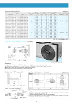
Specifications of geared motor • Each point indicated in the mounting positions shown in Figure 45AD-6 represents (starting at top) the oil plug (PT1) , oil level (VB) , and drain (PT1) . • The mounting positions correspond to code i for the indexing drives. • The oil capacities indicated in Figure 45AD-6 are given in general figures and will differ according to the profile of the cam and the number of cam followers.
Open the catalog to page 21All SANKYO catalogs and technical brochures
 RCC Series
8 Pages
 RW series
8 Pages
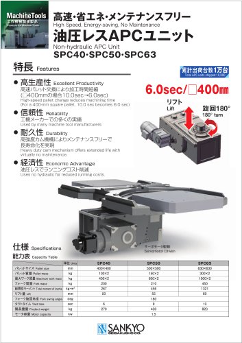 SPC Series
2 Pages
 TCU Series
2 Pages
 RSD Series
1 Page
 EX Series
1 Page
 DSS Series
1 Page
 DST Series
1 Page
 VS-s Series
2 Pages
 CNC Series
16 Pages
 ECO Series
32 Pages
 Large RU Series
24 Pages
 RU Series
28 Pages
 RE series
20 Pages
 Precision adjustable feed Variax
12 Pages
 SANDEX
8 Pages
 RollerDrive
28 Pages
 Do series
7 Pages
 DT, DTR series
11 Pages
 RY series
16 Pages
 RA series
32 Pages


Archived catalogs

- Coaxial gearhead
- Precision gearhead
- Compact gearhead
- Feeder
- Turntable
- Shaft gearhead
- Electric rotary table
- Low-backlash gearhead
- Motor-driven rotary table
- Vibrating feeder
- Vertical rotary table
- Cam indexer
- Rotary indexer
- CNC rotary table
- Mounted gear reducer
- Machine indexer
- Tilting rotary table
- Linear feeder
- Roller feeder