UCNBK65

UCNBK65
General Description and Overview
The UCNBK series aerial cam units are precision-engineered mechanical assemblies designed primarily for piercing and flange applications. They feature a high-rigidity box structure with a V-shaped guide to ensure slider stability. Available mounting widths include 65mm, 100mm, and 200mm, with multiple model variants identified by catalog numbers such as UCNBK65-30 through UCNBK65-70.
1. Components and Materials
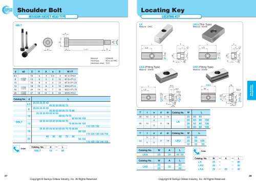
- Main Components: Cam slider, cam driver, cam holder, upper plates, positive return followers, stopper plate, spring guide pin, coil spring, various plates (including cam bottom guide and slide plates), and stoppers.
- Materials: Sliding and structural parts primarily use FC250 cast iron with graphite for low friction; S45C (1045 steel) for followers, plates, and stopper plates; SCM435 steel for spring guide pins; bronze with graphite for guide plates; and urethane for stoppers.
- Bolts: Assembly bolts are referenced (e.g., SOUK65-30 / 35) but not detailed in the document.
2. Mechanical Specifications and Dimensions
- Travel Range: Varies by model from approximately 33.5 mm to 65 mm.
- Working Force: Initial working forces range from 19.6 kN (2.0 tonf) up to 54.5 kN (5.5 tonf), with allowable forces specified for 300,000 strokes to ensure durability.
- Spring Details: Coil springs used include models TL30-125 and TL30-100, with spring constants around 23.76 N/mm (2.42 kgf/mm) or 29.69 N/mm (3.03 kgf/mm) depending on the variant.
- Spring Durability: Guidelines specify durability from 300,000 to 1,000,000 strokes depending on spring type and model.
- Deflection and Lengths: Initial spring deflections range from 10 to 18 mm; free spring lengths are typically 100 or 125 mm; lengths at initial and final loads are provided for precise setup.
- Dimensional Details: Includes hole sizes (e.g., 2-h10H7, 4-h13-h20), dowel pin hole specifications, plate thicknesses, and mounting hole details with references to detailed pages for tapped holes and dowel pins.
3. Performance Data
- Working Force and Load: Each model specifies initial and final loads in Newtons and kilogram-force, with corresponding spring forces and return forces.
- Spring Force at Punch Retraction: Defined as 'z', representing the spring force when the punch retracts 5 mm; 'e' denotes the spring return amount at this retraction.
- Working Life: Standard working force ratings are for one million strokes; allowable working forces are rated for 300,000 strokes to ensure reliability.
4. Assembly and Disassembly Procedures
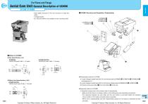
- Disassembly: Loosen hexagon socket head bolts to remove plates and dowel pins, then pull the cam slider rearward from the cam holder.
- Assembly: Reverse disassembly steps, ensuring sliding areas are clean and free of foreign matter. Clearance between cam slider and holder is controlled by matching stamped serial numbers. All provided bolts must be reassembled to maintain structural integrity.
- Options: A key for the holder (option code 'K') can be attached but is not pre-assembled. Detailed specifications for tapped holes and dowel pin holes are referenced for proper installation.
- Space Requirements: Specific space is required for removal of keys and components, with further details referenced in the document.
5. Component Tables and Materials
- Detailed tables list each component’s quantity, material, and remarks to aid manufacturing and maintenance.
- Key materials include FC250 with graphite for sliding parts, S45C for structural components, SCM435 for guide pins, bronze with graphite for guide plates, and urethane for stoppers.
6. Recommendations and Best Practices
- Maintain cleanliness of sliding areas during assembly to ensure performance and longevity.
- Match serial numbers on cam slider and holder to maintain proper clearance and function.
- Use all provided bolts during reassembly to ensure structural integrity.
- Select springs according to required travel and working force to maintain durability.
- Follow specified tolerances and hole finishes for proper assembly and function.
- Refer to detailed pages for hole specifications and key details to ensure correct installation.
- Monitor spring deflection and load parameters during maintenance to prevent premature failure.
Summary
The UCNBK aerial cam units are robust, modular mechanical components designed for piercing and flange applications, offering multiple size options and detailed assembly instructions. Comprehensive performance data and strict material and dimensional specifications ensure reliable operation and longevity. Adherence to assembly procedures, maintenance guidelines, and spring durability recommendations is critical for optimal performance.
Copyright © Sankyo Oilless Industry, Inc. All Rights Reserved.
Catalog excerpts
Aerial Cam Unit General Description of UCNBK OUTLINE OF UCNBK Y High rigidity because of the box structure to keep the qUCNBK Structure and Assembly / Disassembly slider. Y V-shaped guide. Y 100 and 200mm are available for the mounting width. 65, UCNBK65,200:y UCNBK100:u UAssembly method of UCNBK 9 Copyright © Sankyo Oilless Industry, Inc. All Rights Reserved. 1) Loosen hexagon socket head bolt ( ) and remove plate (UCNBK65:!2 UCNBK100:!4 UCNBK200:!3) and dowel pin ( ). 2) Loosen hexagon socket head bolt ( ) and remove stopper plate (UCNBK65,200:y UCNBK100:u). 3) Pull and remove cam slider (q) from cam holder (e) to the rear. Disassembly method of UCNBK U U Metric Key Specification (-KA) 14 UCNBK100/200 LKE25-32-50 (with 3-M8 p 15 bolts) der is attached. embled to the main unit.) 1) Assemble components in the reverse order of disassembly. YMake sure that there is no foreign matter on the sliding area and assemble components. YThe clearance between the cam slider and the cam holder is controlled. Match the stamped serial number on the holder and slider before assembly. YWhen cam is disassembled and then reassembled, please do not forget to assemble all bolts provided. Copyright © Sankyo Oilless Industry, Inc. All Rights Reserved.
Open the catalog to page 1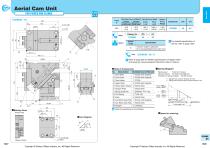
Aerial Cam Unit( FOR PIERCE AND FLANGE Catalog No. | (W) (K)UCNBK 65-00 Cam Units Option Code For detailed specification of the key, refer to page 1035. Order UCNBK65 - 00 - K ^ Refer to page 559 for detailed specifications of tapped holes and dowel pin holes (prepared hole,finish hole) for retainer. ■Spring Diagram □ Bolts for assembly are not indicated. 1037 1038 Copyright © Sankyo Oilless Industry, Inc. All Rights Reserved. Copyright © Sankyo Oilless Industry, Inc. All Rights Reserved.
Open the catalog to page 2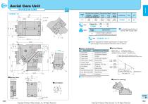
Aerial Cam Unit( FOR PIERCE AND FLANGE Catalog No. | (W) (K)UCNBK 65 - 05 Cam Units Option Code For detailed specification of the key, refer to page 1035. Order UCNBK65 - 05 - K ^ Refer to page 559 for detailed specifications of tapped holes and dowel pin holes (prepared hole,finish hole) for retainer. □ Bolts for assembly are not indicated. UCNBK 65 1039 1040 Copyright © Sankyo Oilless Industry, Inc. All Rights Reserved. Copyright © Sankyo Oilless Industry, Inc. All Rights Reserved.
Open the catalog to page 3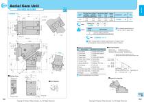
Aerial Cam Unit( FOR PIERCE AND FLANGE Catalog No. | (W) (K)UCNBK 65 - 10 Cam Units Option Code For detailed specification of the key, refer to page 1035. Order UCNBK65 - 10 - K ^ Refer to page 559 for detailed specifications of tapped holes and dowel pin holes (prepared hole,finish hole) for retainer. □ Bolts for assembly are not indicated. UCNBK 65 1041 1042 Copyright © Sankyo Oilless Industry, Inc. All Rights Reserved. Copyright © Sankyo Oilless Industry, Inc. All Rights Reserved.
Open the catalog to page 4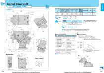
Aerial Cam Unit( FOR PIERCE AND FLANGE Catalog No. | (W) (K)UCNBK 65 - 15 Cam Units Option Code For detailed specification of the key, refer to page 1035. Order UCNBK65 - 15 - K ^ Refer to page 559 for detailed specifications of tapped holes and dowel pin holes (prepared hole,finish hole) for retainer. □ Bolts for assembly are not indicated. UCNBK 65 1043 1044 Copyright © Sankyo Oilless Industry, Inc. All Rights Reserved. Copyright © Sankyo Oilless Industry, Inc. All Rights Reserved.
Open the catalog to page 5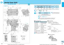
Aerial Cam Unit( FOR PIERCE AND FLANGE Catalog No. | (W) (K)UCNBK 65 - 20 Cam Units Option Code For detailed specification of the key, refer to page 1035. Order UCNBK65 - 20 - K ^ Refer to page 559 for detailed specifications of tapped holes and dowel pin holes (prepared hole,finish hole) for retainer. □ Bolts for assembly are not indicated. UCNBK 65 1045 1046 Copyright © Sankyo Oilless Industry, Inc. All Rights Reserved. Copyright © Sankyo Oilless Industry, Inc. All Rights Reserved.
Open the catalog to page 6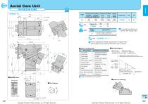
Aerial Cam Unit( FOR PIERCE AND FLANGE _1 Catalog No. | (W) (K)UCNBK 65 - 25 Cam Units Option Code For detailed specification of the key, refer to page 1035. Order UCNBK65 - 25 - K ^ Refer to page 559 for detailed specifications of tapped holes and dowel pin holes (prepared hole,finish hole) for retainer. □ Bolts for assembly are not indicated. UCNBK 65 1047 1048 Copyright © Sankyo Oilless Industry, Inc. All Rights Reserved. Copyright © Sankyo Oilless Industry, Inc. All Rights Reserved.
Open the catalog to page 7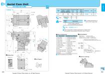
Aerial Cam Unit( FOR PIERCE AND FLANGE Catalog No. | (W) (K)UCNBK 65 - 30 Cam Units Option Code For detailed specification of the key, refer to page 1035. Order UCNBK65 - 30 - K ^ Refer to page 559 for detailed specifications of tapped holes and dowel pin holes (prepared hole,finish hole) for retainer. □ Bolts for assembly are not indicated. UCNBK 65 1049 1050 Copyright © Sankyo Oilless Industry, Inc. All Rights Reserved. Copyright © Sankyo Oilless Industry, Inc. All Rights Reserved.
Open the catalog to page 8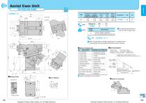
Aerial Cam Unit( FOR PIERCE AND FLANGE Catalog No. | (W) (K)UCNBK 65 - 35 Cam Units Option Code For detailed specification of the key, refer to page 1035. Order UCNBK65 - 35 - K ^ Refer to page 559 for detailed specifications of tapped holes and dowel pin holes (prepared hole,finish hole) for retainer. □ Bolts for assembly are not indicated. UCNBK 65 1051 1052 Copyright © Sankyo Oilless Industry, Inc. All Rights Reserved. Copyright © Sankyo Oilless Industry, Inc. All Rights Reserved.
Open the catalog to page 9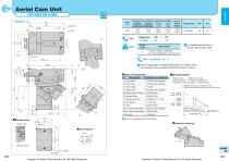
Aerial Cam Unit( FOR PIERCE AND FLANGE _1 ■Cam Diagram Catalog No. | (W) (K)UCNBK 65-40 Cam Units Option Code For detailed specification of the key, refer to page 1035. Order UCNBK65 - 40 - K ^ Refer to page 559 for detailed specifications of tapped holes and dowel pin holes (prepared hole,finish hole) for retainer. □ Bolts for assembly are not indicated. 1053 1054 Copyright © Sankyo Oilless Industry, Inc. All Rights Reserved. Copyright © Sankyo Oilless Industry, Inc. All Rights Reserved.
Open the catalog to page 10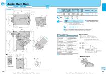
Aerial Cam Unit( FOR PIERCE AND FLANGE _1 ■Backup Area ■Cam Diagram Catalog No. | (W) (K)UCNBK 65-45 Cam Units Option Code For detailed specification of the key, refer to page 1035. Order UCNBK65 - 45 - K ^ Refer to page 559 for detailed specifications of tapped holes and dowel pin holes (prepared hole,finish hole) for retainer. □ Bolts for assembly are not indicated. 1055 1056 Copyright © Sankyo Oilless Industry, Inc. All Rights Reserved. Copyright © Sankyo Oilless Industry, Inc. All Rights Reserved.
Open the catalog to page 11All Sankyo Oilless Industry catalogs and technical brochures
 UCNBK100
16 Pages
 UCNBK200
16 Pages
 SOUK200
16 Pages
 SOUK100
16 Pages
 SOUK65
16 Pages
 UCMSC F150
17 Pages
 UCMSC150
17 Pages
 UCMSC
UCMSC17 Pages
 UCMSC80
17 Pages
 UCMSC65
16 Pages
 UCMSC50
16 Pages
 HUCTF
HUCTF17 Pages
 SULNC
SULNC8 Pages
 SACE
SACE14 Pages
 SUCD
SUCD18 Pages
 SACLB80
2 Pages
 blanking die system
4 Pages
 General Description of Cam Unit
20 Pages
 SESF
SESF1 Page
 SACD
SACD14 Pages
 SLSD
SLSD12 Pages
 SESW / SESWT
1 Page
 TSP
TSP1 Page
 Stroke End Block
1 Page
 Spring Plunger
1 Page
 Feed Sensor
1 Page
 Locating Cone
1 Page
 Bush Flange type:SOBF
2 Pages
 Rubber Spring:SRX,SRXT
6 Pages
 HLSGC
HLSGC1 Page
 CBSL, CBSPL
1 Page
 Guide pin
1 Page
 SOB
SOB4 Pages
 SBLT
SBLT1 Page