UCMSC80

UCMSC80
General Description
The document provides a detailed technical overview of the UCMSC series aerial cam units, specifically models UCMSC80 and UCMSC150, manufactured by Sankyo Oilless Industry, Inc. These cam units are engineered for piercing applications, emphasizing high durability, precision, and reliability in industrial settings.
Structure and Assembly/Disassembly Procedures
Disassembly: Remove hexagon socket head bolts and washers to detach safety and stopper plates, then slide the cam slider rearward out of the cam holder.
Assembly: Reassemble components in reverse order, ensuring sliding surfaces are clean and free of foreign matter. Clearance between guide bar, cam slider, and cam holder is controlled by matching stamped serial numbers on the holder and slider. All bolts must be reinstalled after disassembly to maintain structural integrity.
Options and Specifications
- Option Codes:
- K: Dedicated key attached but not assembled to the main unit.
- SC: Mount surface extension adjustable from 0 to 60 mm in 1 mm increments.
- WC: Mount width modification to 100 mm or 120 mm (WC100 or WC120).
- N16: Dowel pin holes for cam holder and driver changed to h16H7 tolerance.
Performance Parameters
- Working Force: Varies by model and travel angle, ranging approximately from 32.1 kN to 98.5 kN.
- Spring Force: Initial load around 270.6 N (27.6 kgf), final load approximately 1623.6 N (165.7 kgf).
- Travel Angles: Specified from 0° up to 60°, affecting force and spring characteristics.
- Total Weight: Between 21.6 kg and 27 kg depending on configuration.
Spring Characteristics
The units utilize TL35-150 springs with a spring constant of 27.06 N/mm (2.76 kgf/mm). Key parameters include:
- Free length: 150 mm
- Length at initial load: 140 mm (10 mm deflection)
- Length at final load: 90 mm
- Stripping force measured at 5 mm punch retraction
- Spring return force also measured at 5 mm punch return
Cam Diagrams and Dimensions
Detailed cam diagrams specify critical dimensions such as mount hole sizes, angles (e.g., 30°, 120°), and machining tolerances (e.g., ±0.02 mm). These ensure precise fitting and smooth operation of the cam units.
Ordering Instructions
When ordering units with the WC option, the piercing center position must be specified within the cam width. Catalog numbers and option codes must be clearly indicated to ensure correct configuration.
Critical Notes and Best Practices
- Maintain cleanliness of sliding surfaces during assembly to prevent malfunction.
- Ensure clearance by matching serial numbers on cam holder and slider.
- Do not omit any bolts during reassembly to preserve structural integrity.
- Use specified springs and adhere strictly to load and travel specifications for optimal performance and longevity.
- If slider protrusion causes interference with the die, machine the die to provide adequate clearance.
Component Materials and Assembly
The document lists components for UCMSC80 and UCMSC150 units, detailing quantities, materials, and remarks. Materials include FCD450, FC250, SS400, S45C (1045), SCM435, bronze with graphite, urethane, SUJ2, and various bolts and springs. Components cover cam holders, sliders, drivers, slide plates, return mechanisms, guide pins, safety plates, keys, stoppers, coil springs, dowel pins, coned disc springs, and bolts, each identified by code and quantity to facilitate assembly and maintenance.
Summary of Key Parameters by Model
| Model | Working Force (kN) | Initial Load (kN) | Final Load (kN) | Spring Force (N) | Total Weight (kg) | Travel Angle (°) |
|---|---|---|---|---|---|---|
| UCMSC 80 30 | 54.3 | 39.2 | 78.4 | 270.6 | 23.2 | 30 |
| UCMSC 80 35 | 57.4 | 39.2 | 78.4 | 270.6 | 23.4 | 35 |
| UCMSC 80 40 | 64.3 | 39.2 | 78.4 | 270.6 | 22.4 | 40 |
| UCMSC 80 45 | 69.6 | 39.2 | 78.4 | 270.6 | 22.4 | 45 |
| UCMSC 80 50 | 77.8 | 39.2 | 78.4 | 270.6 | 21.6 | 50 |
| UCMSC 80 55 | 87.2 | 39.2 | 78.4 | 270.6 | 21.7 | 55 |
| UCMSC 80 60 | 98.5 | 39.2 | 78.4 | 270.6 | 23.2 | 60 |
Performance and Durability
The cam units are rated for a standard working force over one million strokes and an allowable working force for 300,000 strokes, ensuring long-term durability and reliability in piercing operations.
Conclusion
This document serves as a comprehensive technical guide for the UCMSC series aerial cam units, covering assembly/disassembly procedures, detailed specifications, spring and load parameters, dimensional data, options for customization, component materials, and ordering instructions. Adherence to the specified parameters and best practices ensures optimal performance, durability, and ease of maintenance for piercing applications.
Catalog excerpts
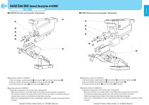
Aerial Cam Unit General Description of UCMSC( FOR PIERCE ■ UCMSC80 Structure and Assembly / Disassembly ■UCMSC150 Structure and Assembly / Disassembly Cam Units 1) Remove hexagon socket head bolt (©) and washer (©), and remove safety plate (©). 2) Remove hexagon socket head bolt (©) and remove stopper plate (©). 3) Pull and remove cam slider (©) from cam holder (©)to the rear. •Assembly method of UCMSC80 1) Assemble components in the reverse order of disassembly. • Make sure that there is no foreign matter on the sliding area and assemble components. •The clearance between the guide bar/cam slider and the cam holder is controlled. Match the stamped serial number on the holder and slider before assembly. •When cam is disassembled and then reassembled, please do not forget to assemble all bolts provided. •Disassembly method of UCMSC150 1) Remove hexagon socket head bolt ©) and washer (©), and remove safety plate (©). 2) Remove hexagon socket head bolt ©) and remove stopper plate (©). 3) Pull and remove cam slider ©) from cam holder (©)to the rear. •Assembly method of UCMSC150 1) Assemble components in the reverse order of disassembl •Make sure that there is no foreign matter on the sliding area and assemble components. •The clearance between the guide bar/cam slider and the cam holder is controlled. Match the stamped serial number on the holder and slider before assembly. •When cam is disassembled and then reassembled, please do not forget to assemble all bolts provided. Copyright © Sankyo Oilless Industry, Inc. All Rights Reserved. Copyright © Sankyo Oilless Industry, Inc. All Rig
Open the catalog to page 1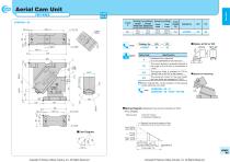
Aerial Cam Unit( FOR PIERCE 3 ■Cam Diagram Copyright © Sankyo Oilless Industry, Inc. All Rights Reserved. Travel S Option Code □ When ordering WC, set the position of the piercing center within the cam width. ■Spring Diagram (Stripping Force at punch retraction of 5mm) • For UCMSC • Spring Used TL35-150(1 Piece) 27.06N/mm(2.76kgf/mm) Final Load Copyright © Sankyo Oilless Industry, Inc. All Rights Reserved. UCMSC 80
Open the catalog to page 2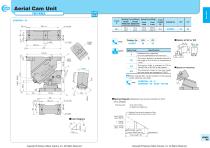
Aerial Cam Unit( FOR PIERCE 3 ■ Option of SC or WC Option Code □ When ordering WC, set the position of the piercing center within the cam width. ■Spring Diagram (Stripping Force at punch retraction of 5mm) • For UCMSC • Spring Used TL35-150(1 Piece) UCMSC 80 Copyright © Sankyo Oilless Industry, Inc. All Rights Reserved. Copyright © Sankyo Oilless Industry, Inc. All Rights Reserved.
Open the catalog to page 3
Aerial Cam Unit( FOR PIERCE 3 Copyright © Sankyo Oilless Industry, Inc. All Rights Reserved. Travel S Option Code □ When ordering WC, set the position of the piercing center within the cam width. ■Space for removing UCMSC80 - 10 - K UCMSC80 - 10 - SC30 - WC100 ■Spring Diagram (Stripping Force at punch retraction of 5mm) • For UCMSC • Spring Used TL35-150(1 Piece) 27.06N/mm(2.76kgf/mm) Final Load Initial Load Copyright © Sankyo Oilless Industry, Inc. All Rights Reserved. UCMSC 80
Open the catalog to page 4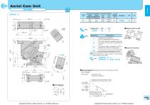
Aerial Cam Unit( FOR PIERCE 3 UCMSC80- 15 Copyright © Sankyo Oilless Industry, Inc. All Rights Reserved. Travel S ■Option of SC or WC Option Code □ When ordering WC, set the position of the piercing center within the cam width. ■Space for removing UCMSC80 - 15 - K UCMSC80 - 15 - SC30 - WC100 ■Spring Diagram (Stripping Force at punch retraction of 5mm) • For UCMSC • Spring Used TL35-150(1 Piece) 27.06N/mm(2.76kgf/mm) Copyright © Sankyo Oilless Industry, Inc. All Rights Reserved. UCMSC 80
Open the catalog to page 5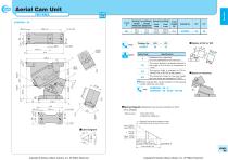
Aerial Cam Unit( FOR PIERCE 3 ■Option of SC or WC Option Code □ When ordering WC, set the position of the piercing center within the cam width. ■Spring Diagram (Stripping Force at punch retraction of 5mm) • For UCMSC • Spring Used TL35-150(1 Piece) 27.06N/mm(2.76kgf/mm) Final Load Initial Load UCMSC 80 Copyright © Sankyo Oilless Industry, Inc. All Rights Reserved. Copyright © Sankyo Oilless Industry, Inc. All Rights Reserved.
Open the catalog to page 6
Aerial Cam Unit( FOR PIERCE 3 Option Code □ When ordering WC, set the position of the piercing center within the cam width. ■Spring Diagram (Stripping Force at punch retraction of 5mm) • For UCMSC •Spring Used TL35-150(1 Piece) 27.06N/mm(2.76kgf/mm) z : Stripping Force at punch retraction of 5mm e : Spring return when the punch return is 5mm UCMSC 80 Copyright © Sankyo Oilless Industry, Inc. All Rights Reserved. Copyright © Sankyo Oilless Industry, Inc. All Rights Reserved.
Open the catalog to page 7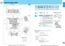
Aerial Cam Unit( FOR PIERCE 3 Option Code □ When ordering WC, set the position of the piercing center within the cam width. ■Spring Diagram (Stripping Force at punch retraction of 5mm) • For UCMSC • Spring Used TL35-150(1 Piece) 27.06N/mm(2.76kgf/mm) Final Load Initial Load UCMSC 80 Copyright © Sankyo Oilless Industry, Inc. All Rights Reserved. Copyright © Sankyo Oilless Industry, Inc. All Rights Reserved.
Open the catalog to page 8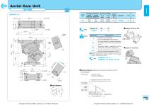
Aerial Cam Unit( FOR PIERCE 3 ■Option of SC or WC Option Code □ When ordering WC, set the position of the piercing center within the cam width. ■Spring Diagram (Stripping Force at punch retraction of 5mm) • For UCMSC •Spring Used TL35-150(1 Piece) UCMSC 80 Copyright © Sankyo Oilless Industry, Inc. All Rights Reserved. Copyright © Sankyo Oilless Industry, Inc. All Rights Reserved.
Open the catalog to page 9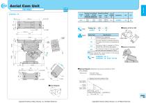
Aerial Cam Unit( FOR PIERCE 3 Copyright © Sankyo Oilless Industry, Inc. All Rights Reserved. Option Code □ When ordering WC, set the position of the piercing center within the cam width. ■Spring Diagram (Stripping Force at punch retraction of 5mm) • For UCMSC • Spring Used TL35-150(1 Piece) 27.06N/mm(2.76kgf/mm) Copyright © Sankyo Oilless Industry, Inc. All Rights Reserved.
Open the catalog to page 10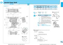
Aerial Cam Unit( FOR PIERCE 3 Copyright © Sankyo Oilless Industry, Inc. All Rights Reserved. Travel S Option Code □ When ordering WC, set the position of the piercing center within the cam width. ■Spring Diagram (Stripping Force at punch retraction of 5mm) • For UCMSC • Spring Used TL35-150(1 Piece) 27.06N/mm(2.76kgf/mm) Final Load Initial Load Copyright © Sankyo Oilless Industry, Inc. All Rights Reserved. UCMSC 80
Open the catalog to page 11All Sankyo Oilless Industry catalogs and technical brochures
 UCNBK100
16 Pages
 UCNBK200
16 Pages
 UCNBK65
16 Pages
 SOUK200
16 Pages
 SOUK100
16 Pages
 SOUK65
16 Pages
 UCMSC F150
17 Pages
 UCMSC150
17 Pages
 UCMSC
UCMSC17 Pages
 UCMSC65
16 Pages
 UCMSC50
16 Pages
 HUCTF
HUCTF17 Pages
 SULNC
SULNC8 Pages
 SACE
SACE14 Pages
 SUCD
SUCD18 Pages
 SACLB80
2 Pages
 blanking die system
4 Pages
 General Description of Cam Unit
20 Pages
 SESF
SESF1 Page
 SACD
SACD14 Pages
 SLSD
SLSD12 Pages
 SESW / SESWT
1 Page
 TSP
TSP1 Page
 Stroke End Block
1 Page
 Spring Plunger
1 Page
 Feed Sensor
1 Page
 Locating Cone
1 Page
 Bush Flange type:SOBF
2 Pages
 Rubber Spring:SRX,SRXT
6 Pages
 HLSGC
HLSGC1 Page
 CBSL, CBSPL
1 Page
 Guide pin
1 Page
 SOB
SOB4 Pages
 SBLT
SBLT1 Page