- Catalogs
- Sankyo Oilless Industry
- UCMSC F150
UCMSC F150
1 /17Pages

UCMSC F150
1 /17Pages
Catalog excerpts
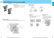
Aerial Cam Unit General Description of UCMSF FOR PIERCE qOption of UCMSF UKey specification(-K) For 80 LKU32-50 (with 1-M8p15 bolts) equal to the cam width and reduction of weight. Y V-shaped guide. Y Available angle is 0˚ to 70˚ at increments of 5˚. U Features of UCMSF Y Space saving design with the mounting width UHome Position kit (-S) UCMSF 150 90±0.05 The jig (q Collar w Bolt e Nut) for locking the bottom dead center is accompanied as shown in the figure below. The stopper plate has tapped 32 3 threads for installation. Spring guide pin Copper alloy bushing Stopper plate Copyright © Sankyo Oilless Industry, Inc. All Rights Reserved. qStructure of UCMSF UCMSF is the 2-stage spring type is used to improve the spring force. Copper alloy for high pressure is used for the cam slide guide (cam bottom) to increase the force. UCMSF 150 T-shaped key grooves are additionally machined as shown in the figure below.
Open the catalog to page 1
Aerial Cam Unit General Description of UCMSF FOR PIERCE qUCMSF80 Structure and Assembly / Disassembly qUCMSF150 Structure and Assembly / Disassembly 1) Remove hexagon socket head bolt ( ) and remove safety plate (!1). 2) Remove hexagon socket head bolt ( ) and remove stopper plate (o). 3) Pull and remove cam slider (w) from cam holder (q)to the rear. tAssembly method of UCMSF80 1) Assemble components in the reverse order of disassembly. Y Make sure that there is no foreign matter on the sliding area and assemble components. YThe clearance between the guide bar/cam slider and the cam holder is...
Open the catalog to page 2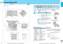
Aerial Cam Unit( FOR PIERCE _1 Catalog No. (W) (K)UCMSF 150 - 00 ITK Option (cam holder) Option Code Refer to page 880 for option details. Order UCMSF150 - 00 - TK ^ Refer to page 559 for detailed specifications of tapped holes and dowel pin holes (prepared hole, finish hole) for retainer. ■Table of Components ■Spring Diagram No. For Final Load •Guideline of spring durability 0 Bolts for assembly are not indicated. ■Space for removing • Spring Used For Initial Load TF40-90 (1 Piece) 27.85N/mm(2.84kgf/mm) TH60-60 (1 Piece) 736.11N/mm(75.06kgf/mm) TF40-90 300,000 strokes TH60-60 500,000...
Open the catalog to page 3
Aerial Cam Unit( FOR PIERCE 1 _1 ^ Refer to page 880 for option details. Order UCMSF150 - 05 - TK Refer to page 559 for detailed specifications of tapped holes and dowel pin holes (prepared hole, finish hole) for retainer. 0 Bolts for assembly are not indicated. ■Space for removing ■Spring Diagram • Spring Used For Initial Load TF40-90 (1 Piece) 27.85N/mm(2.84kgf/mm) For Final Load TH60-60 (1 Piece) 736.11N/mm(75.06kgf/mm) •Guideline of spring durability TF40-90 300,000 strokes Copyright © Sankyo Oilless Industry, Inc. All Rights Reserved. Copyright © Sankyo Oilless Industry, Inc. All...
Open the catalog to page 4
Aerial Cam Unit( FOR PIERCE _1 Catalog No. (W) (K)UCMSF 150 — 10 ITK Option (cam holder) Option Code Refer to page 880 for option details. Order UCMSF150 - 10 - TK ^ Refer to page 559 for detailed specifications of tapped holes and dowel pin holes (prepared hole, finish hole) for retainer. ■Table of Components ■Spring Diagram No. For Final Load •Guideline of spring durability 0 Bolts for assembly are not indicated. ■Space for removing • Spring Used For Initial Load TF40-90 (1 Piece) 27.85N/mm(2.84kgf/mm) TH60-60 (1 Piece) 736.11N/mm(75.06kgf/mm) TF40-90 300,000 strokes TH60-60 500,000...
Open the catalog to page 5
Aerial Cam Unit( FOR PIERCE _1 Catalog No. (W) (K)UCMSF 150 — 15 ITK Option (cam holder) Option Code Refer to page 880 for option details. Order UCMSF150 - 15 - TK ^ Refer to page 559 for detailed specifications of tapped holes and dowel pin holes (prepared hole, finish hole) for retainer. 0 Bolts for assembly are not indicated. ■Space for removing ■Spring Diagram • Spring Used For Initial Load TF40-90 (1 Piece) 27.85N/mm(2.84kgf/mm) For Final Load TH60-60 (1 Piece) 736.11N/mm(75.06kgf/mm) •Guideline of spring durability TF40-90 300,000 strokes UCMSF 150 919 920 Copyright © Sankyo...
Open the catalog to page 6
Aerial Cam Unit( FOR PIERCE _1 UCMSF150 - 20 ■Cam Diagram Travel S Catalog No. (W) (K)UCMSF 150 — 20 ITK Option (cam holder) Option Code Refer to page 880 for option details. Order UCMSF150 - 20 - TK ^ Refer to page 559 for detailed specifications of tapped holes and dowel pin holes (prepared hole, finish hole) for retainer. 0 Bolts for assembly are not indicated. ■Space for removing ■Spring Diagram • Spring Used For Initial Load TF40-90 (1 Piece) 27.85N/mm(2.84kgf/mm) For Final Load TH60-60 (1 Piece) 736.11N/mm(75.06kgf/mm) •Guideline of spring durability TF40-90 300,000 strokes...
Open the catalog to page 7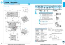
Aerial Cam Unit( FOR PIERCE _1 Catalog No. (W) (K)UCMSF 150 — 25 ITK Option (cam holder) Option Code Refer to page 880 for option details. Order UCMSF150 - 25 - TK ^ Refer to page 559 for detailed specifications of tapped holes and dowel pin holes (prepared hole, finish hole) for retainer. 0 Bolts for assembly are not indicated. ■Space for removing ■Spring Diagram • Spring Used For Initial Load TF40-90 (1 Piece) 27.85N/mm(2.84kgf/mm) For Final Load TH60-60 (1 Piece) 736.11N/mm(75.06kgf/mm) •Guideline of spring durability TF40-90 300,000 strokes UCMSF 150 923 924 Copyright © Sankyo...
Open the catalog to page 8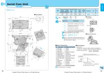
Aerial Cam Unit( FOR PIERCE _1 ■Cam Diagram Travel S Option Code Refer to page 880 for option details. Order UCMSF150 - 30 - TK ^ Refer to page 559 for detailed specifications of tapped holes and dowel pin holes (prepared hole, finish hole) for retainer. 0 Bolts for assembly are not indicated. ■Spring Diagram ■Space for removing • Spring Used For Initial Load TF40-90 (1 Piece) 27.85N/mm(2.84kgf/mm) For Final Load TH60-60 (1 Piece) 736.11N/mm(75.06kgf/mm) •Guideline of spring durability TF40-90 300,000 strokes Copyright © Sankyo Oilless Industry, Inc. All Rights Reserved. Copyright © Sankyo...
Open the catalog to page 9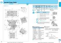
Aerial Cam Unit( FOR PIERCE _1 f \UCMSF150 - 35 ■Cam Diagram Travel S Catalog No. (W) (K)UCMSF 150 - 35 ITK Option (cam holder) Option Code Refer to page 880 for option details. Order UCMSF150 - 35 - TK ^ Refer to page 559 for detailed specifications of tapped holes and dowel pin holes (prepared hole, finish hole) for retainer. Bolts for assembly are not indicated. ■Space for removing ■Spring Diagram • Spring Used For Initial Load TF40-90 (1 Piece) 27.85N/mm(2.84kgf/mm) For Final Load TH60-60 (1 Piece) 736.11N/mm(75.06kgf/mm) •Guideline of spring durability TF40-90 300,000 strokes...
Open the catalog to page 10All Sankyo Oilless Industry catalogs and technical brochures
 UCNBK100
16 Pages
 UCNBK200
16 Pages
 UCNBK65
16 Pages
 SOUK200
16 Pages
 SOUK100
16 Pages
 SOUK65
16 Pages
 UCMSC150
17 Pages
 UCMSC
UCMSC17 Pages
 UCMSC80
17 Pages
 UCMSC65
16 Pages
 UCMSC50
16 Pages
 HUCTF
HUCTF17 Pages
 SULNC
SULNC8 Pages
 SACE
SACE14 Pages
 SUCD
SUCD18 Pages
 SACLB80
2 Pages
 blanking die system
4 Pages
 General Description of Cam Unit
20 Pages
 SESF
SESF1 Page
 SACD
SACD14 Pages
 SLSD
SLSD12 Pages
 SESW / SESWT
1 Page
 TSP
TSP1 Page
 Stroke End Block
1 Page
 Spring Plunger
1 Page
 Feed Sensor
1 Page
 Locating Cone
1 Page
 Bush Flange type:SOBF
2 Pages
 Rubber Spring:SRX,SRXT
6 Pages
 HLSGC
HLSGC1 Page
 CBSL, CBSPL
1 Page
 Guide pin
1 Page
 SOB
SOB4 Pages
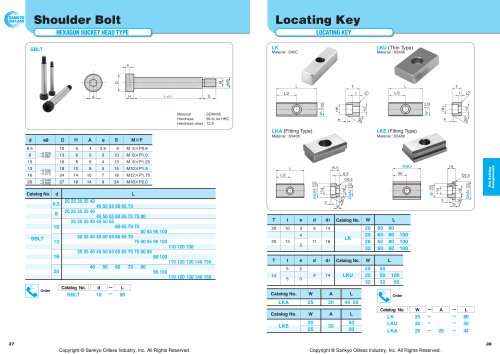
 SBLT
SBLT1 Page