

SACE

SACE
Catalog excerpts
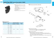
Aerial Cam Unit General Description of SACE( WORKING FORCE 3-TON TYPE ~) •The standard working force (one million strokes) achieved 29.4 kN with the mounting width of 52 mm. The allowable working force (300,000 strokes) is 58.8 kN. • I mproved durability of coil springs compared to old products.(SACD) •V-shaped guide. •Available angle is 0°to 60°at increments of 5° •Disassembly method of SACE52 1) Remove hexagon socket head bolt (©), and remove stopper plate (©). 2) Pull and remove cam slider (©) from cam holder (O) to the rear. •A ssembly method of SACE52 1)Assemble components in the reverse order of disassembly. • Make sure that there is no foreign matter on the sliding area and assemble components. • The clearance between the cam slider and the cam holder is controlled. Match the stamped serial number on the holder and slider before assembly. • When cam is disassembled and then reassembled,please do not forget to assemble all bolts provided. Copyright © Sankyo Oilless Industry, Inc. All Rights Reserved. Copyright © Sankyo Oilless Industry, Inc. All Rights Reserv
Open the catalog to page 1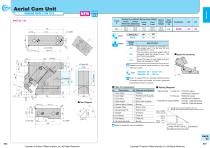
Aerial Cam Unit ( WORKING FORCE 3-TON TYPE ) rrm CAD FILE f ASACE 52 - 00 Travel S Option Code 0 Determine the pierce center position in the range of the cam width. ■Space for removing SACE52 - 00 - SC40 - N12 SACE52- 00 - WC120 Refer to page 559 for detailed specifications of tapped holes and dowel pin holes (prepared hole,finished hole) for retainer. 0 Bolts for assembly are not indicated. ■ Spring Diagram • Spring Used For Initial Load TF20-90(1 piece) 7.01N/mm(0.72kgf/mm) For Final Load TM30-50(1 piece) 109.65N/mm(11.18kgf/mm) • Guideline of spring durability TF20-90 1,000,000 strokes TM30-50...
Open the catalog to page 2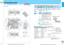
Aerial Cam Unit ( WORKING FORCE 3-TON TYPE ) rrm CAD FILE f ASACE 52 - 05 Travel S Option Code 0 Determine the pierce center position in the range of the cam width. ■Space for removing SACE52 - 05 - SC40 - N12 SACE52 - 05 - WC120 Refer to page 559 for detailed specifications of tapped holes and dowel pin holes (prepared hole,finished hole) for retainer. 0 Bolts for assembly are not indicated. ■ Spring Diagram • Spring Used For Initial Load TF20-90(1 piece) 7.01N/mm(0.72kgf/mm) For Final Load TM30-50(1 piece) 109.65N/mm(11.18kgf/mm) • Guideline of spring durability TF20-90 1,000,000 strokes TM30-50...
Open the catalog to page 3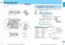
Aerial Cam Unit ( WORKING FORCE 3-TON TYPE Catalog No. | | (W) | — (K) SACE 52 - 10 Option Code 0 Determine the pierce center position in the range of the cam width. Refer to page 559 for detailed specifications of tapped holes and dowel pin holes (prepared hole,finished hole) for retainer. ■ Spring Diagram • Spring Used For Initial Load For Final Load • Guideline of spring durability 0 Bolts for assembly are not indicated. Copyright © Sankyo Oilless Industry, Inc. All Rights Reserved. Copyright © Sankyo Oilless Industry, Inc. All Rights Reserved.
Open the catalog to page 4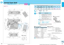
Aerial Cam Unit ( WORKING FORCE 3-TON TYPE Catalog No. | | (W) | — (K) SACE 52 - 15 Option Code 0 Determine the pierce center position in the range of the cam width. ■Space for removing SACE52 - 15 - SC40 - N12 SACE52 - 15 - WC120 Refer to page 559 for detailed specifications of tapped holes and dowel pin holes (prepared hole,finished hole) for retainer. 0 Bolts for assembly are not indicated. ■ Spring Diagram • Spring Used For Initial Load TF20-90(1 piece) 7.01N/mm(0.72kgf/mm) For Final Load TM30-50(1 piece) 109.65N/mm(11.18kgf/mm) • Guideline of spring durability TF20-90 1,000,000...
Open the catalog to page 5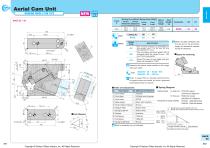
Aerial Cam Unit( WORKING FORCE 3-TON TYPE ) rrm CAD FILE Option Code □ When the slider interferes with the die due to the protrusion length, you will need to machine the die for clearance. 0 Determine the pierce center position in the range of the cam width. ■Space for removing SACE52 - 20 - SC40 - N12 SACE52 - 20 - WC120 Refer to page 559 for detailed specifications of tapped holes and dowel pin holes (prepared hole,finished hole) for retainer. 0 Bolts for assembly are not indicated. ■ Spring Diagram • Spring Used For Initial Load TF20-90(1 piece) 7.01N/mm(0.72kgf/mm) For Final Load TM30-50(1...
Open the catalog to page 6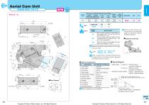
Aerial Cam Unit( WORKING FORCE 3-TON TYPE ) rrm CAD FILE Option Code 0 When the slider interferes with the die due to the protrusion length, you will need to machine the die for clearance. 0 Determine the pierce center position in the range of the cam width. ■Space for removing SACE52 - 25 - SC40 - N12 SACE52 - 25 - WC120 Refer to page 559 for detailed specifications of tapped holes and dowel pin holes (prepared hole,finished hole) for retainer. 0 Bolts for assembly are not indicated. ■ Spring Diagram • Spring Used For Initial Load TF20-90(1 piece) 7.01N/mm(0.72kgf/mm) For Final Load TM30-50(1...
Open the catalog to page 7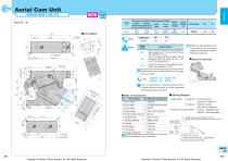
Aerial Cam Unit ( WORKING FORCE 3-TON TYPE ) rrm CAD FILE f ASACE 52 - 30 Travel S Option Code 0 When the slider interferes with the die due to the protrusion length, you will need to machine the die for clearance. 0 Determine the pierce center position in the range of the cam width. ■Space for removing SACE52 - 30 - SC40 - N12 SACE52 - 30 - WC120 Refer to page 559 for detailed specifications of tapped holes and dowel pin holes (prepared hole,finished hole) for retainer. 0 Bolts for assembly are not indicated. ■ Spring Diagram • Spring Used For Initial Load TF20-90(1 piece) 7.01N/mm(0.72kgf/mm) For...
Open the catalog to page 8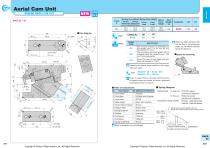
Aerial Cam Unit( WORKING FORCE 3-TON TYPE ) rrm CAD FILE Option Code 0 When the slider interferes with the die due to the protrusion length, you will need to machine the die for clearance. 0 Determine the pierce center position in the range of the cam width. ■Space for removing SACE52 - 35 - SC40 - N12 SACE52 - 35 - WC120 Refer to page 559 for detailed specifications of tapped holes and dowel pin holes (prepared hole,finished hole) for retainer. 0 Bolts for assembly are not indicated. ■ Spring Diagram • Spring Used For Initial Load TF20-90(1 piece) 7.01N/mm(0.72kgf/mm) For Final Load TM30-50(1...
Open the catalog to page 9All Sankyo Oilless Industry catalogs and technical brochures
 UCNBK100
16 Pages
 UCNBK200
16 Pages
 UCNBK65
16 Pages
 SOUK200
16 Pages
 SOUK100
16 Pages
 SOUK65
16 Pages
 UCMSC F150
17 Pages
 UCMSC150
17 Pages
 UCMSC
UCMSC17 Pages
 UCMSC80
17 Pages
 UCMSC65
16 Pages
 UCMSC50
16 Pages
 HUCTF
HUCTF17 Pages
 SULNC
SULNC8 Pages
 SUCD
SUCD18 Pages
 SACLB80
2 Pages
 blanking die system
4 Pages
 General Description of Cam Unit
20 Pages
 SESF
SESF1 Page
 SACD
SACD14 Pages
 SLSD
SLSD12 Pages
 SESW / SESWT
1 Page
 TSP
TSP1 Page
 Stroke End Block
1 Page
 Spring Plunger
1 Page
 Feed Sensor
1 Page
 Locating Cone
1 Page
 Bush Flange type:SOBF
2 Pages
 Rubber Spring:SRX,SRXT
6 Pages
 HLSGC
HLSGC1 Page
 CBSL, CBSPL
1 Page
 Guide pin
1 Page
 SOB
SOB4 Pages
 SBLT
SBLT1 Page




- VirtualExpo Group
- Our Partners
- Recruitment
- Testimonials