- Catalogs
- Sankyo Oilless Industry
- General Description of Cam Unit
General Description of Cam Unit
1 /20Pages

General Description of Cam Unit
1 /20Pages
Catalog excerpts
•Compact design with the mounting width of 52 mm and the shut height of 125 mm. • Automatic alignment mechanism of the V-shaped guide. •Available angle is 0°to 80° at increments of 5°. Copyright © Sankyo Oilless Industry, Inc. All Rights Reserved. Copyright © Sankyo Oilless Industry, Inc. All Rights Reserved.
Open the catalog to page 1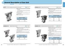
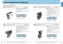
General Description of Cam Unit OVER VIEW Cam Units HUCTF For thick metal pierce reinforced return force type ^P.683~716 UCMSC80-150 Standard Type for Pierce ^P.787~850 •Strong type with spring force of about 6000 N-600 kgf. It is most suitable for piercing of high strength steel and thick steel. • Automatic alignment mechanism of the V-shaped guide. •Available angle is 0° to 75° at increments of 5°. • ISO springs are used. Copyright © Sankyo Oilless Industry, Inc. All Rights Reserved. Copyright © Sankyo Oilless Industry, Inc. All Rights Reserved. 542
Open the catalog to page 2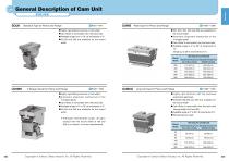
General Description of Cam Unit OVER VIEW Cam Units SOUK Standard Type for Pierce and Flange ^P.851~944 SUWB Wide Type For Pierce and Flange ^P.1007~1098 • Highly rigid sliding structure of cam slider. •Cam Slider is removable from the back side. •Available angle is 0° to 70° at increments of 5°. • 65,100 and 200 are available for the mount width. • 200, 300, 400, 500 and 600 are available for the mount width. • Automatic alignment mechanism of the V-shaped guide. •Cam Slider is removable from the back side. •Available angle is 0° to 60° at increments of 10°. Copyright © Sankyo Oilless Industry,...
Open the catalog to page 3
General Description of Cam Unit OVER VIEW I Types and Features of Die Mounted Cam Unit Cam Units UCMSL Large and Long Life Type For Pierce and Flange ^P. 1267—1352 CMSD Compact Type For Pierce ^P. 1555—1574 •500 to 1000 at the increments of 100 mm are available for the mount width. •Available angle is 0° to 60° at increments of 10°. • 52 and 90 are available for the mount width. • Easy to remove the cam slider. •Available angle is 0° to 20° at increments of 5°. (Up to 15°for CMSD90) Mount Width Mount Width UCMSNR NAAMS standards for pierce and flange ^P.1353—1486 SKC/SKCA Standard Type...
Open the catalog to page 4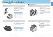
General Description of Cam Unit OVER VIEW ISpecial Die Mounted Cam Unit Cam Units KGSP Long Life Type For Pierce and Flange WCMSH/WCMS Double Cam Unit Series • Highly rigid structure with the overseas automobile manufacturer specification. •52,80,150,200 and 300 are available for the mount width. •Available angle is 0°to 30° at increments of 5°. • ISO springs are used. CTCS/CTCH2CTVS/CTVH Thrust Cam Unit Series ^P.1789—1798 Copyright © Sankyo Oilless Industry, Inc. All Rights Reserved. Copyright © Sankyo Oilless Industry, Inc. All Rights Reserved. • Use of integrated rigid casting design •The...
Open the catalog to page 5
General Description of Cam Unit OVER VIEW Available for large cam or dedicated cam to customer's specification. List of cam unit option ^■Code SC Cat.No SC In addition to standard cam units, customized cam units may be manufactured. Large cams or dedicated cams are products that can satisfy requirements of customers for module units on dies. Reduction of lead time, indirect costs, etc. contributes to die manufacturing of customers. Large Cam Cams which have conventionally been manufactured together with dies are separated into units. Dies are simplified and cam units are customized to order....
Open the catalog to page 6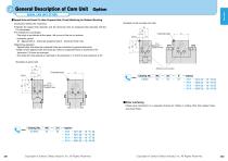
General Description of Cam Unit( AERIAL CAM UNIT OPTION ~") Option ■Tapped Hole and Dowel Pin Hole (Prepared Hole, Finish) Machining for Retainer Mounting • Instruction method for machining • Indicate the tapped hole diameter and the dowel pin hole (or prepared hole) diameter with the XY coordinates. •To indicate the coordinates •The origin is positioned at the upper l eft corner of the mo unt surface. • Indication symbol M...Tapped hole,K...Dowel pin prepared hole,N...Dowel pin finish hole • Machining standard •Tapped holes and dowel pin prepared holes are machined to general tolerances. •Depth...
Open the catalog to page 7
OVER VIEW Calculation Formula of Force Applied to Aerial Cam Unit θ : Working angle 1 2 θ : Cam Angle F : Force Required for Working (Working Force + Spring Return Force + Pad Force) P : Press force V : Load Applied to Cam Driver Surface Q : Load Applied to Cam Slider Surface S : Travel S' : Spring Travel L : Press Travel Locating and Installation Procedure of Pierce Punch (retainer) in Aerial Cam Unit General Description of Cam Unit Drill the mounting holes and dowel pin holes (finish) on the die for the cam holder and the driver. Fix the cam holder and the driver on the die with bolts and dowel...
Open the catalog to page 8
General Description of Cam Unit OVER VIEW ■Calculation Formula of Force Applied to Die Mounted Cam Unit Cam Units 0 : Working Angle 0i : Driver Inclination Angle F : Force Required for Working (Working force + Spring Return Force + Pad Force) P : Press Force V : Load Applied to Cam Driver Surface Q : Load applied to Cam Slider Ssurface S : Working Travel L : Press Travel Cam Diagram •No Inclination of Working Angle (0") Copyright © Sankyo Oilless Industry, Inc. All Rights Reserved. Copyright © Sankyo Oilless Industry, Inc. All Rights Reserved. 556
Open the catalog to page 9
General Description of Cam Unit Guide Line for Selection (Aerial Cam) OVER VIEW (Mount width) 1000 900 800 700 600 500 400 300 200 165 150 100 80 70 65 52 50
Open the catalog to page 10
Guide Line for Selection (Die Mounted Cam) General Description of Cam Unit< OVER VIEW - (Working Force tonf) Copyright © Sankyo Oilless Industry, Inc. All Rights Reserved. Copyright © Sankyo Oilless Industry, Inc. All Rights Reserved. 560
Open the catalog to page 11
General Description of Cam UnitAERIAL CAM UNIT SELECTION TABLE ") Cam Units 561 Copyright © Sankyo Oilless Industry, Inc. All Rights Reserved. Copyright © Sankyo Oilless Industry, Inc. All Rights Reserved. 562
Open the catalog to page 12All Sankyo Oilless Industry catalogs and technical brochures
 UCNBK100
16 Pages
 UCNBK200
16 Pages
 UCNBK65
16 Pages
 SOUK200
16 Pages
 SOUK100
16 Pages
 SOUK65
16 Pages
 UCMSC F150
17 Pages
 UCMSC150
17 Pages
 UCMSC
UCMSC17 Pages
 UCMSC80
17 Pages
 UCMSC65
16 Pages
 UCMSC50
16 Pages
 HUCTF
HUCTF17 Pages
 SULNC
SULNC8 Pages
 SACE
SACE14 Pages
 SUCD
SUCD18 Pages
 SACLB80
2 Pages
 blanking die system
4 Pages
 SESF
SESF1 Page
 SACD
SACD14 Pages
 SLSD
SLSD12 Pages
 SESW / SESWT
1 Page
 TSP
TSP1 Page
 Stroke End Block
1 Page
 Spring Plunger
1 Page
 Feed Sensor
1 Page
 Locating Cone
1 Page
 Bush Flange type:SOBF
2 Pages
 Rubber Spring:SRX,SRXT
6 Pages
 HLSGC
HLSGC1 Page
 CBSL, CBSPL
1 Page
 Guide pin
1 Page
 SOB
SOB4 Pages
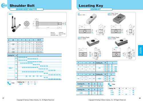
 SBLT
SBLT1 Page