
- Catalogs
- SANKYO OILLESS INDUSTRY,INC.
- Spherical Bush Set

Spherical Bush Set

Spherical Bush Set
This document provides detailed instructions and specifications for the assembly and operation of an oilless spherical bushing unit. The key components include the inner ring, outer ring, and hexagon socket head screws.
Assembly and Fixing Method
- Insert the unit at the specified shaft position and secure the inner ring and shaft with set screws.
- Fix the case with bolts, ensuring the mating part is suitable for operating conditions and free of foreign matter.
- For installations with three or more units, align the shaft with a tolerance of +/-0.25 mm.
Fixing Method of Shaft and Inner Ring
- Position the inner ring to avoid contact with the outer ring end, maintaining a clearance of 0.1 mm.
- In environments with vibration or impact, provide seating at the set screw position.
Handling Thrust Load
- Use a flange type inner ring for thrust load applications, ensuring the flange area aligns with the solid lubricant surface.
Greasing
- A grease groove is provided on the outer ring to enhance wear resistance and durability.
Accuracy and Design of Shaft
- The recommended tolerance for the mating shaft is g6. Material and hardness are not critical, and heat treatment is not required.
Measures for Heat Generation
- For high-temperature applications, consider thermal expansion in the thrust direction and design the flange outside if using a flange type inner ring.
Specifications and Materials
- Inner ring: S45C
- Outer ring: Bronze with graphite oilless type (SO#50SP2)
- Hexagon socket head screw: SCM435
Dimensional Tolerances
The document provides detailed dimensional tolerances for various components, ensuring precise assembly and operation.
RoHS Compliance
The unit is designed to minimize thrust from the inner flange type bushing, with solid lubricant embedded on the outer ring edge. A stopper pin for the outer ring is included.
Catalog excerpts
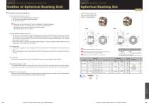
Outline of Spherical Bushing Unit For operation of spherical bushing unit (1) Assembly and xing method of unit Insert the unit at the specied position of the shaft. Fix the inner ring and the shaft with set screws. Fix the case with bolts. Spherical Bushing Set SBSF (Inner Ring Flange Type) SBSS (Inner Ring Straight Type) SBSR ( , Outer Ring Only) Make sure that the mating part for the unit is suitable for operating conditions. Be careful that there is no foreign matter or step on the mounting surface. • When three units or more are used, align the shaft correctly. (The tolerance should be +/-0.25 mm.) • S Recommended mating post tolerance is g6 Outer ring Stopper pin for outer ring (SUJ2 1pce) is attached. (4) For greasing Grease groove is provided at the outer ring. Greasing can improve wear resistance and durability. To minimize thrust from the inner flange type bushing, solid lubricant is embedded on the outer ring edge. Inner ring Hexagon socket head screw 2 Bronze with graphite oilless type(SO#50SP2) SCM435 SBSF SBSS Outer ring SBSF SBSR Outer ring (6) Measures for heat generation If the unit is used at high temperature, thermal expansion (thrust direction) of the shaft occurs. If the ange type inner ring is used, it is recommended to design the ange outside. (5) Accuracy and design of shaft The recommended tolerance of the mating shaft is g6. Since the inner ring slides with the outer ring, material and hardness of the shaft is not particularly important. Heat treatment of the shaft surface is not required either. Slide Unit (3) For thrust load If thrust load is applied, use the ange type inner ring. Solid lubricant is embedded at one side of the outer ring. When a ange type is used, make assembly so that the ange area may match the solid lubricant surface at the side. (2) Fixing method of shaft and inner ring Fix the inner ring at the position where the ange does not come in contact with the outer ring end. Fix it with the clearance of 0.1 mm as a guideline. If interference between the inner ring ange and the outer ring end due to thermal expansion/shrink of the shaft is concerned, adjust the clearance appropriately. (One straight type screw per position is used) If the unit is used at a place or environment where vibration or impact is applied, provide seating at the set screw position of the shaft with a le or borer.
Open the catalog to page 1All SANKYO OILLESS INDUSTRY,INC. catalogs and technical brochures
 PSCL,PSCM
1 Page
 SHPUC
SHPUC3 Pages
 SACE
SACE14 Pages
 TSHC
TSHC2 Pages
 SACLB80
2 Pages
 SUCD
SUCD18 Pages
 SHCP
SHCP1 Page
 SNR41,42,43 Series
1 Page
 SFCU,SFCUB
1 Page
 CBSL,CBSPL
1 Page
 MCUW,MCUF,MCUS
1 Page
 TWP
TWP1 Page
 Parallel Link Unit
1 Page
 Single Link Unit
1 Page
 Cam Slide Guide (L Type)
1 Page
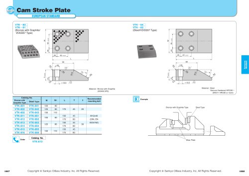 Cam Stroke Plate
1 Page
 Roller Cam Unit
2 Pages
 Roller Cam Unit
2 Pages
 Side Gauge
1 Page
 DA Gauge
1 Page
 Spring Plunger
1 Page
 Spring Plunger
1 Page
 Feed Sensor
1 Page
 Locating Cone
1 Page
 Shoulder Bolt
1 Page
 Slide Plate Blank Type
1 Page
 Guide Bushing
2 Pages
 Ejector Guide Bushing
1 Page
 Ejector Guide Pin
2 Pages
 Automatic Blanking Die
4 Pages
 Die Materials
2 Pages
 Aerial Cam Unit For Pierce
18 Pages
 Slide Plate VSM SP2,ST
1 Page
 Lifting Hook(Eye Bolt)
1 Page
 Shim Plate
1 Page
 Ball Guide Bushing
1 Page




Archived catalogs
 General Description of Cam Unit
20 Pages
 LARGE TYPE FOR PIERCE AND FLANGE
15 Pages
 Ball Plunger
1 Page


- Measuring device
- Lifting system
- Metal chain
- Industrial measuring module
- Plain bearing
- Mechanical buffer
- Anti-vibration damper
- Metal plain bearing
- Plastic buffer
- Metal bushing
- Cutting tool
- Guide rail
- Self-lubricating plain bearing
- Plastic plain bearing
- Compact buffer
- Rubber absorber
- Steel rail
- Spring plunger
- Steel plain bearing
- Slide rail