- Catalogs
- Sankyo America
- GV, GI & GII Series, Linear Walking Beam
GV, GI & GII Series, Linear Walking Beam
1 /21Pages

GV, GI & GII Series, Linear Walking Beam
1 /21Pages
Catalog excerpts

Parts Handler Model code example Timing number Gill type Timing of input and output (Modified Trapezoid] (Modified Sine) (Modified Constant Motion Curve special order A right hand cam or left hand cam for parts handler is determined by the first direction of stroke I of the output arm when the input shaft is rotated from the base position (at 0°) as specified on the time chart. m Right hand can!|| |/ ^ Gill type Gill type
Open the catalog to page 1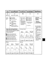
Input shaft projection Mounting holes Mounting position Special instructions Both Tand U surface 31 Both T and U surface sides T surface side input IB2I U surface side input m Both T and U surface input extention and reducer mounted •Certain models have limi- tation on the surfaces that can be drilled with mount- (Always refer to the page Output, input shaft specification An optional miniature motor is available for the GY series and model 6GV. A miter gearbox can be attached to models 6GY and 6GV. (Custom order specification.) Mounting the miniature motor ISMi Input shaft on one side, mounted...
Open the catalog to page 2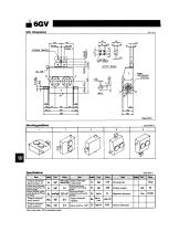
Mounting positions _Figure 6GV-2 Note : Input inertia: GD2 is calculated in dwell.
Open the catalog to page 3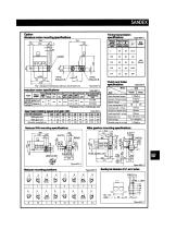
Miniature motor mounting specifications The * indicates the dimensions without a clutch/ brake unit. Timing transmission
Open the catalog to page 4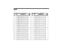
Carrying capacity table of stroke I for mounting position 1.2.3 or 4 Table GGV-I
Open the catalog to page 5
STROKE CENTER ACRYLIC COVER Mounting positions Note: Input inertia : GD2 is calculated in dwell.
Open the catalog to page 6
OlltpUt blOCk Figure 8GI-3 Mounting hole dimension of R and W surface
Open the catalog to page 7
Carrying capacity table of stroke I for mounting position 1.3 or 4 Table SGI 1 Carrying capacity table of stroke I for mounting position 5 or 6 Table SG|-2
Open the catalog to page 8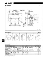
STROKE CENTER Mounting positions Specifications Table SGIM Note: Input inertia: GD2 Is calculated in dwell.
Open the catalog to page 9
Output block Figure 8GII-3 Mounting hole dimension of S and W surface INPUT SHAFT INPUT SHAFT Locations of oil plug Figure 8GII-5 Reducer R66 mounting specifications Reducer mounting positions
Open the catalog to page 10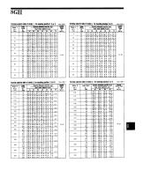
Carrying capacity table of stroke I for mounting position 1,3 or 4 Table eon
Open the catalog to page 11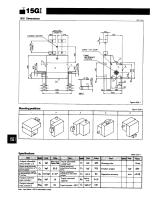
STROKE CENTER Note : Input inertia : GD2 is calculated in dwell.
Open the catalog to page 12
Output blOCk Figure 15GI 3 Mounting hole dimension of R and W surface INPUT SHAFT LOCatiOnS Of Oil plug Figure 15GI-5 Reducer R100 mounting specifications Reducw mounting potHons
Open the catalog to page 13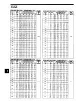
Carrying capacity table of stroke I for mounting position 1,3 or 4 Table ISGM
Open the catalog to page 14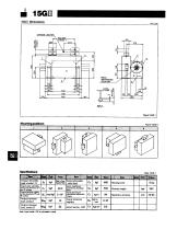
STROKE CENTER Note: Input inertia: GD2 is calculated in dwell.
Open the catalog to page 15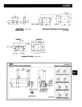
Output block Figure 15GII-3 Mounting hole dimension of R and W surface INPUT SHAFT OIL LEVEL OIL DRAIN " 0IL LEVEL Locations Of Oil plug Figure 15GII-5 Reducer R100 mounting specifications Reducer mounting positions
Open the catalog to page 16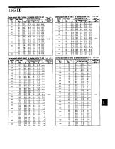
Carrying capacity table of stroke I for mounting position 1.3 or 4 table ISGM Carrying capacity table of stroke I for mounting position 5 or 6 Table ISGH-2
Open the catalog to page 17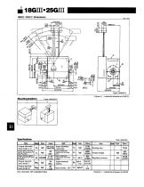
•Figures in ( ) indicate the dimensions for 25G III. Mounting positions Note: Input inertia: GD2 is calculated in dwell. •Figures in ( ) indicate the dimensions for 25G HI.
Open the catalog to page 18
•Figures in ( ) indicate the dimensions for 25G III. Mounting hole dimension of R and W surface INPUT SHAFT Reducer R125 (R160) mounting specifications •Figures in ( ) indicate the dimensions for 25G III when mounting the R160. Reducer mounting positions
Open the catalog to page 19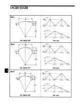
Over lapping chart Over lapping chart Time chart Over lapping chart Time chart
Open the catalog to page 20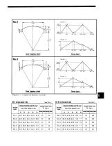
• Figures in ( ) indicate the dimension for 25GIII. 18GI Carrying capacity table 25GI Carrying capacity table
Open the catalog to page 21All Sankyo America catalogs and technical brochures
 The Zero-Backlash Technology
32 Pages
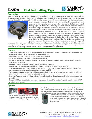 Do Series, Ring Indexer
4 Pages
 Coil Feeds for Presses
23 Pages
 RE Series Catalog
20 Pages
 RA Series Catalog
22 Pages
 P Series Catalog
2 Pages
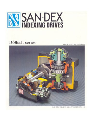 D Series Catalog
24 Pages
 ED Series Catalog
1 Page
 DT/RT/DTR Series Catalog
5 Pages
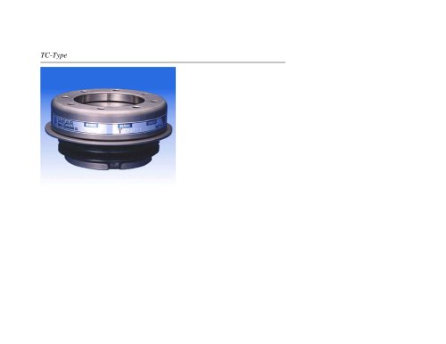 TC Series Catalog
11 Pages
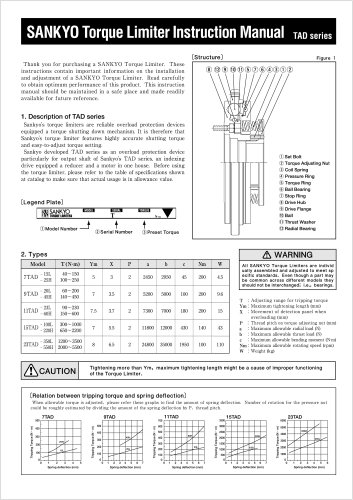 TAD Alpha Catalog
2 Pages
 GY Series Catalog
20 Pages


Archived catalogs
 Eco Series ED Catalog
32 Pages
 Alpha Series Catalog
25 Pages
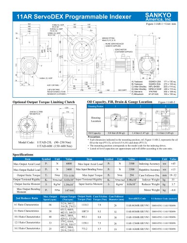
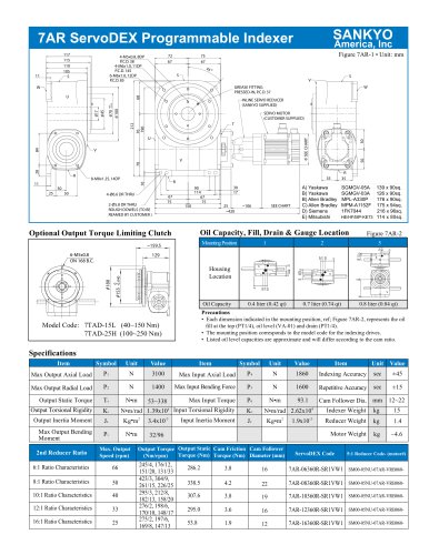
 Alpha Servo Catalog
18 Pages
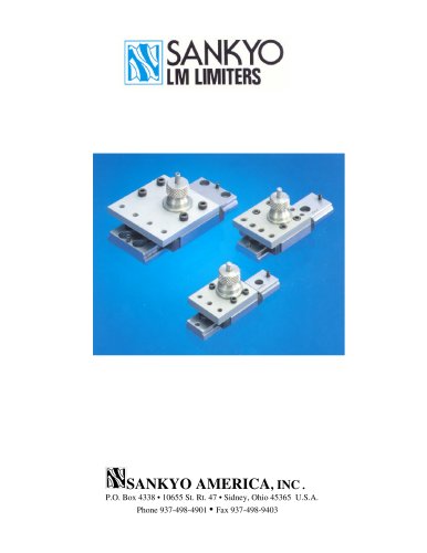 LM Series Catalog
8 Pages
 DF, EF & RF Series Catalog
19 Pages
 D, E & R Series Catalog
18 Pages
- Rail conveyor
- Transport rail conveyor
- Horizontal conveyor
- Feeder
- Turntable
- Chain conveyor
- Electric rotary table
- Horizontal rotary table
- Motor-driven rotary table
- Mounting machine
- Overload clutch
- Automatic assembling machine
- Tool changer
- Index unit
- Vertical rotary table
- Machine tool rotary table
- Cam indexer
- Rotary indexer
- CNC rotary table
- Automatic tool changer