- Catalogs
- Sankyo America
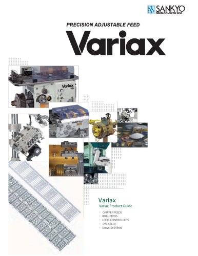
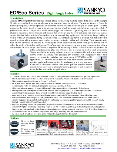
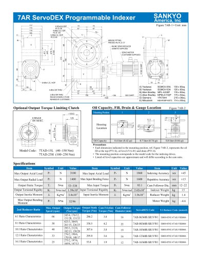
- FU Series, Rotary with Lift, Extended Stroke
FU Series, Rotary with Lift, Extended Stroke

FU Series, Rotary with Lift, Extended Stroke
Catalog excerpts

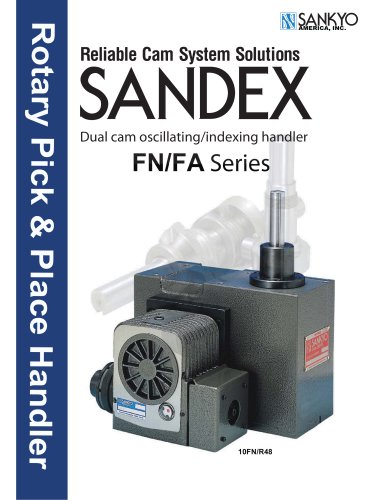
Reliable Cam System Solutions Single cam oscillating/indexing handler
Open the catalog to page 1
Rotary Indexing or Oscillating Unit SANKYO Innovation Features & Options Rotary Part Handler Features Featuring 20~70mm lift strokes, 30º~60º indexing & 30º~180º oscillating motions. High torque capacity with speed up to 60 cycles/min. Large selection of 5 compact cast iron housing sizes. Mounts horizontal, vertical or inverted. Globoidal cam design for rotational motion with synchronized face cam for lift motions. Cam motions are integrated with gripper actuation response times with the drive running continuously. x Up to 60 cycles per minute x 20~70mm lift stroke motions; ±0.2~0.5mm x 30º~60º...
Open the catalog to page 2
Rotary Indexing or Oscillating Unit SANKYO Innovation Features & Options VFD Controller Option Variable frequency drives combined with brushless motors are maintenance-free. Electronic braking eliminates brake dust contamination and ensures consistent braking while protecting the motor from overheating. x x x x x Electronic braking is maintenance free Enables frequent stop/starting cycles Variable speed control on the fly Motor protection with thermal feedback Preset speeds for jog setup or emergency stop recovery can avoid tooling damage x External braking resister option for frequent stop/start...
Open the catalog to page 3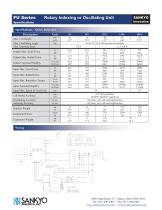
Rotary Indexing or Oscillating Unit -DWELL BETEPTDP
Open the catalog to page 4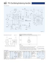
7FU Oscillating/Indexing Handler 7FU Dimensions TIMING REFERENCE POSITION Locations of oil plug, ets., and oil capacity Mounting hole locations Mounting position Each point indicated in the mounting positions shown in Figure 7FU-3 represents (starting at top) the oil plug (PT3/8), oil level (VA-01), and drain (PT3 /8). The mounting positions correspond to code i for the indexing, o scillating, and roller drives. The oil levels indicated in Figure 7FU-3 are given in general gures and will differ according to the prole of the cam and the number of cam follow ers. Specications Item Output allowable...
Open the catalog to page 5
Oscillating handler Torque transmission capacity table Reading the capacity table for oscillating handler The capacity table gives dynamic torque To and dynamic allowable load Wo by oscillating angles, number of stops, life, and rotatingspeed. This table was calculated based on a life expectancy of 12,000 hours of normal operationincluding mounting, lubrication, and handling conditions. Adverse conditions and poor maintenance can affect the transmission capacity and life of the oscillate handler. Beside, if you misunderstandhow to read the capacity table when you select a model, you are not able...
Open the catalog to page 6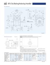
8FU Oscillating/Indexing Handler 8FU Dimensions T TIMING REFERENCE POSITION Locations of oil plug, ets., and oil capacity Mounting hole locations Mounting position Precautions Each point indicated in the mounting positions shown in Figure 8FU-3 represents (starting at top) the oil plug (PT3/8), oil level (VA-01), and drain (PT3 /8). The mounting positions correspond to code i for the indexing, o scillating, and roller drives. The oil levels indicated in Figure 8FU-3 are given in general gures and will differ according to the prole of the cam and the number of cam follow ers. Specications Item...
Open the catalog to page 7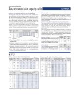
Oscillating handler Torque transmission capacity table Reading the capacity table for oscillating handler The capacity table gives dynamic torque To and dynamic allowable load Wo by oscillating angles, number of stops, life, and rotatingspeed. This table was calculated based on a life expectancy of 12,000 hours of normal operationincluding mounting, lubrication, and handling conditions. Adverse conditions and poor maintenance can affect the transmission capacity and life of the oscillate handler. Beside, if you misunderstandhow to read the capacity table when you select a model, you are not able...
Open the catalog to page 8
11FU Oscillating/Indexing Handler 11FU Dimensions W T TIMING REFERENCE POSITION Locations of oil plug, ets., and oil capacity Mounting hole locations Mounting position Each point indicated in the mounting positions shown in Figure 11FU-3 represents (starting at top) the oil plug (PT1/2), oil level (VA), and dra in (PT1/2). The mounting positions correspond to code i for the indexing, o scillating, and roller drives. The oil levels indicated in Figure 11FU-3 are given in general gures and will differ according to the prole of the cam and the number of cam follow ers. Specications Item Output allowable...
Open the catalog to page 9
Oscillating handler Torque transmission capacity table Reading the capacity table for oscillating handler The capacity table gives dynamic torque To and dynamic allowable load Wo by oscillating angles, number of stops, life, and rotatingspeed. This table was calculated based on a life expectancy of 12,000 hours of normal operationincluding mounting, lubrication, and handling conditions. Adverse conditions and poor maintenance can affect the transmission capacity and life of the oscillate handler. Beside, if you misunderstandhow to read the capacity table when you select a model, you are not able...
Open the catalog to page 10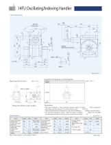
14FU Oscillating/Indexing Handler 14FU Dimensions W T TIMING REFERENCE POSITION Locations of oil plug, ets., and oil capacity Mounting hole locations Mounting position Precautions Each point indicated in the mounting positions shown in Figure 14FU-3 represents (starting at top) the oil plug (PT1/2), oil level (VA), and dra in (PT1/2). The mounting positions correspond to code i for the indexing, o scillating, and roller drives. The oil levels indicated in Figure 14FU-3 are given in general gures and will differ according to the prole of the cam and the number of cam follow ers. Specications Item...
Open the catalog to page 11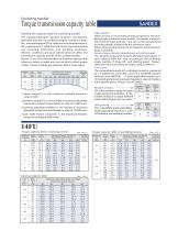
Oscillating handler Torque transmission capacity table Reading the capacity table for oscillating handler The capacity table gives dynamic torque To and dynamic allowable load Wo by oscillating angles, number of stops, life, and rotatingspeed. This table was calculated based on a life expectancy of 12,000 hours of normal operationincluding mounting, lubrication, and handling conditions. Adverse conditions and poor maintenance can affect the transmission capacity and life of the oscillate handler. Beside, if you misunderstandhow to read the capacity table when you select a model, you are not able...
Open the catalog to page 12All Sankyo America catalogs and technical brochures
 The Zero-Backlash Technology
32 Pages
 Do Series, Ring Indexer
4 Pages
 Coil Feeds for Presses
23 Pages
 RE Series Catalog
20 Pages
 RA Series Catalog
22 Pages
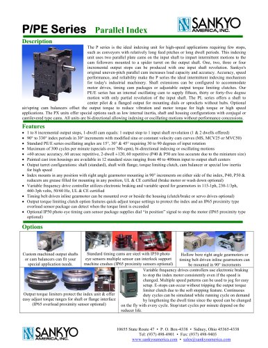 P Series Catalog
2 Pages
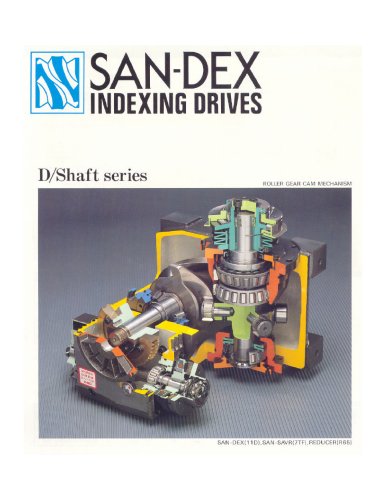 D Series Catalog
24 Pages
 ED Series Catalog
1 Page
 DT/RT/DTR Series Catalog
5 Pages
 TC Series Catalog
11 Pages
 TAD Alpha Catalog
2 Pages
 GY Series Catalog
20 Pages


Archived catalogs
 Eco Series ED Catalog
32 Pages
 Alpha Series Catalog
25 Pages
 Alpha Servo Catalog
18 Pages
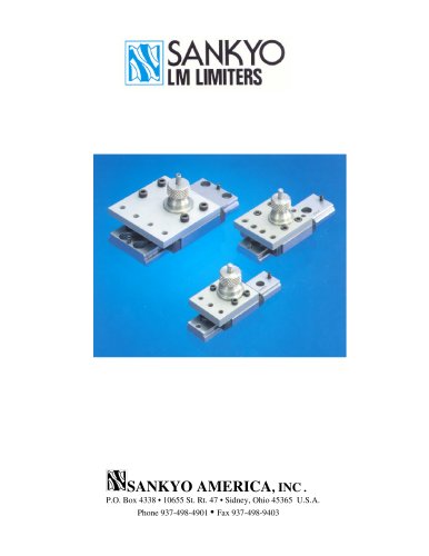 LM Series Catalog
8 Pages
 DF, EF & RF Series Catalog
19 Pages
 D, E & R Series Catalog
18 Pages
- Transport rail conveyor
- Horizontal conveyor
- Feeder
- Turntable
- Chain conveyor
- Electric rotary table
- Horizontal rotary table
- Motor-driven rotary table
- Overload clutch
- Automatic assembling machine
- Tool changer
- Index unit
- Vertical rotary table
- Machine tool rotary table
- Cam indexer
- Rotary indexer
- CNC rotary table
- Automatic tool changer