
- Catalogs
- Sankyo America
- D Series Catalog

D Series Catalog
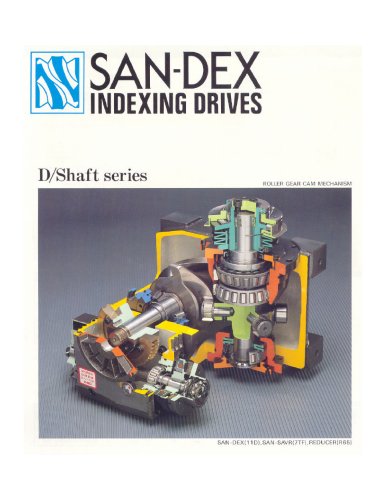
D Series Catalog
Technical Specifications and Dimensions
This section details the mechanical and performance parameters for indexing drive models 4.5D/4.5E/4.5R, 6D/6E/6R, 7D/7E/7R, and 8D/8E/8R. Key parameters include output allowable axial loads ranging from 784 N to 2156 N, indexing accuracy varying by dwell count (e.g., ±60 seconds for 4.5D, ±30 seconds for 7D at 1 dwell), repetitive accuracy, product weights from 30 kg to 63.7 kg, and consistent gray housing color. Additional specifications cover maximum bending forces, torques, radial loads, static torque, torsional rigidity, and inertia values.
Mounting and Installation
Precise mounting hole locations and surface dimensions are specified with tight tolerances (h6, h7, h8 fits). Illustrations provide guidance for mounting motors, torque limiters, reducers, and accessories. Motors are typically mounted on sides T or U. Torque limiters (6TF, 6TC, 7TF, 7TC) and reducers (R48, R65) are compatible with various models, with TC-type torque limiters and reducers requiring collars for proper installation.
Lubrication and Maintenance
The 4.5D model is permanently grease-lubricated and maintenance-free. Other models specify oil plug, oil level, and drain locations, with oil capacities dependent on cam profile and number of cam followers. Proper lubrication is critical for performance and longevity.
Motor and Gearhead Specifications
Specifications for Oriental and Panasonic induction motors include rotational speeds, allowable torque, output power, capacitor values, starting torque, voltage, current, and rated torque. Gearhead models and reduction ratios must be specified when ordering. Timing transmission details cover pulley reduction ratios, number of teeth, and belt types.
Accuracy and Performance
Indexing accuracy is provided for 1 to 4 dwell points, with repetitive accuracy typically at 15 seconds. Torsional rigidity and static torque values are included to assess load performance.
Precautions and Recommendations
- Always specify gear reduction ratio with the indexing drive code when ordering.
- Use collars when mounting torque limiter TC-types and reducers.
- Check oil levels according to cam profile and follower count.
- Mount motors on designated sides (T or U) as per installation figures.
- Consult manufacturer brochures for detailed motor specifications.
Summary of Critical Data Tables
Tables 4.5D-1, 6D-1, 7D-1, and 8D-1 provide comprehensive mechanical and performance data per model series. Tables 4.5D-2/3 and 6D-2/3 list motor allowable torque values at various speeds and gear ratios.
Illustrations and Figures
Figures 4.5D-1 to 4.5D-5, 6D-1 to 6D-5, 7D-1 to 7D-4, and 8D-1 to 8D-3 include dimensional drawings, mounting hole locations, accessory mounting, lubrication points, and motor mounting configurations, supporting precise installation and integration.
Models and Accessories Compatibility
- Models 8D, 8E, 8R support torque limiters 7TF, 8TF, 7TC, 8TC.
- Models 11D, 11E, 11R support reducers R65, R80 and torque limiters 7TF, 8TF, 11TF, 7TC, 8TC, 11TC.
- Models 14D, 14E, 14R support reducers R65, R80, R100 and torque limiters 8TF, 11TF, 14TF, 8TC, 11TC, 14TC.
- Models 17D, 17E, 17R support reducers R80, R100 and torque limiters 11TF, 14TF, 11TC, 14TC.
- Models 18D, 18R support reducers R80, R100, R125 and torque limiters 11TF, 14TF, 18TF, 11TC, 14TC, 18TC.
- Collars are mandatory for mounting TC-type torque limiters and reducers.
Mounting Positions and Precautions
- Reducers can be mounted in 16 different positions, each with specific codes for indexing, oscillating, and roller drives.
- Oil plug, oil level, and drain points correspond to mounting positions and are detailed in figures (e.g., 11D-3, 14D-3).
- Oil levels depend on cam profile and follower count.
- Collars are required for certain torque limiters and reducers.
Dimensional Data and Mounting Hole Locations
Detailed dimensional drawings specify shaft diameters, bolt sizes, and surface dimensions for each model series (e.g., Figures 8D-1, 11D-1, 14D-1).
Performance Specifications
| Parameter | Symbol | Unit | Typical Range |
|---|---|---|---|
| Output allowable axial load | P1 | N | 4900 to 14700 |
| Input allowable axial load | P2 | N | 314 to 1441 |
| Indexing accuracy (1 to 4 dwells) | Ts | sec | ±30 to ±120 |
| Repetitive accuracy | K1 | sec | 15 |
| Product weight | kg | 15 to 220 | |
| Input max repetitious bending force | P3 | N | 167 to 931 |
| Input max repetitious allowable torque | P4 | N·m | 3528 to 10241 |
| Output allowable radial load | P5 | N | 2842 to 5782 |
| Output static torque | P6 | N·m | 30,400 to 137,000 |
| Output torsional rigidity | K2 | N·m/rad | 0.007 to 0.195 |
| Input torsional rigidity | J1 | N·m/rad | ±30 to ±120 |
Note: Values vary by model and configuration; consult specific tables for exact data.
Oil Capacity and Lubrication Points
- Oil capacities range from approximately 0.9 to 10 liters depending on model and mounting position.
- Standardized oil plug, oil level, and drain locations are indicated in model-specific figures.
- Maintaining correct oil level based on cam profile and follower count is essential for optimal operation.
Example Model Codes
- 8D 12272R LR3VW 1 / 40 RCB 3 / 1 / 7 TF 25 B
- 11D 12272R LR3VW 1 / 40 RA 15 / 1 / 7 TC 20 B
- 14D 12272R LR3VW 1 / 40 RCB 15 / 1 / 11 TF 85 B
- 17D 12272R LR3VW 5 / 40 RA 14 / 5 / 11 TC 100 B
- 18D 12272R LR3VW 1 / 40 RA 15 / 1 / 14 TF 180 B
Critical Notes and Best Practices
- Always use collars when mounting torque limiter TC-types and reducers to ensure proper installation and function.
- Verify mounting positions to align with lubrication points for correct oil management.
- Check oil levels according to cam profile and follower count to maintain performance.
- Select torque limiters and reducers based on torque capacity tables matching load requirements.
- Consult detailed dimensional drawings before assembly to ensure compatibility.
Summary
This document is a comprehensive technical reference for selecting, mounting, and configuring indexing drives with reducers and torque limiters across multiple model series. It emphasizes correct mounting positions, lubrication management, accessory compatibility, and detailed performance specifications to ensure reliable, accurate, and efficient operation.
Catalog excerpts

INDEXING DRIVES
Open the catalog to page 1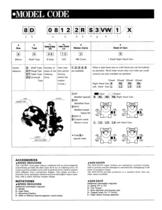
•MODEL CODE • SPEED REDUCERS The "CAVEX" worm gear reducer combined with an electromagnetic clutch/brake provides the ideal input drive for an indexing drive. Its concave profile cylinder worm with its globoid worm wheel is substan- tially different from conventional designs. This design provides a smoother drive, minimizes vibration and provides higher output capac- ities, with a highly-efficient compact design. • SPEED REDUCERS Additional information required: B—Gear Ratio C—Mounting Position D—With or Without Electromagnetic clutch/brake The SAN-SAVR torgue limiters are mechanical overload...
Open the catalog to page 2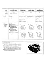
Input Shaft Projection Mounting Holes Mounting Position Special Instructions Tapped mounting holes on surfaces V and W come auto- matically. In addition, tapped mounting holes on the other surface are also available as shown below. [T]Only T surface side [2] Only U surface side [3] Both T and U surface sides I R1 IT surface side input I R2 |U surface side input [ R3 I Both T and U surface input • Mounting holes supplied on surfaces V and W come automatically. Upon request, the mounting holes can be placed on surfaces R,S,T • Model code shows the assembly of cam and turret, together with output,...
Open the catalog to page 3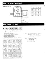
•MOTOR ADAPTOR •MODEL CODE b: Nominal speed ratio (Note 1) * As coded, worm is right hand gear only. c: Options for reducer (Note 2) d: Mounting posture (see below) e: Posture of index drive (see index drive catalogs) Note 1 The code which is placed in square " b" represents the nominal speed ratio. Both nominal and actual speed ratio can be found in the specification table of each reducer. without clutch & brake with brake only with clutch only with clutch & brake
Open the catalog to page 4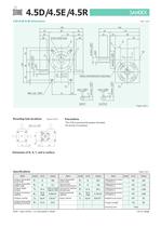
4.5D/4.5E/4.5R 4.5D/4.5E/4.5R Dimensions (Unit : mm) 160 35 150 90 35 34 45 26 40 34 110 32 18 90 26 STOP POSITION 45 S c d W T 65h8 ( +0.000 ) -0.046 U 17 110 14h6 ( +0.000 ) -0.011 130 45 45 T V 20 +0.000 16h6 ( -0.011 ) S b a V 5N9 ( +0.000 ) -0.030 70 10 3 M8x1.25, 15DP. INPUT 3 16h6 ( +0.000 ) -0.011 R 14h6 ( +0.000 ) -0.011 10 40 INDEX REFERENCE POSITION R 5N9 (+0.000 ) -0.030 OUTPUT Figure 4.5D-1 Mounting hole locations Figure 4.5D-2 ·The 4.5D is permanently grease lubricated. No servise is necessary. 70 10 10 70 M8x1.25, 15DP R Precautions T 10 110 Dimension of R, S, T, and U surface...
Open the catalog to page 5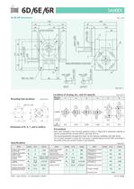
6D/6E/6R 6D/6E/6R Dimensions (Unit : mm) 190 40 55 40 38 STOP POSITION 30 c 18 120 60 S W T d b a 20 60 55 T 146 16h6 (+0.000 ) -0.011 170 20h6 (+0.000 ) -0.013 S U 140 32 75h8 (+0.000 ) -0.046 38 30 180 110 25 40 V 55 INDEX REFERENCE POSITION 86 12 3 M8x1.25, 15DP. 7N9 ( +0.000 ) -0.036 INPUT 20h6 ( +0.000 ) -0.013 5N9 (+0.000) -0.030 4 R 16h6 ( +0.000 ) -0.011 12 V R OUTPUT Figure 6D-1 Locations of oil plug, etc., and oil capacity Mounting hole locations Figure 6D-2 Mounting position 1 2 96 75 55 T 12 86 12 3 4 5 6 78 55 M8x1.25, 15DP. R Figure 6D-3 12 146 Location 88 58 15 0 S 80 60 0 32 62...
Open the catalog to page 9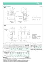
Mounted accessories Figure 6D-4 6D(c) 197 180 110 40 47 120 55 60 92) Example Model Code D TIMING PULLEY L100B Indexing Drive 6D — 06122R — SM3VW TIMING BELT 1 Motor Mounting Code ( 90 330 275 55 60 170 55 COVER 5IK90GU—AF — 40 — 1 200 (202) TIMING PULLEY L100A 59 259 (261) 118 6D(d) 197 55 110 47 170 60 55 40 55 COVER 180 60 120 TIMING PULLEY L100B Indexing Drive 92) 6D — 06122R — SM3VW TIMING BELT 5IK90GU—AF 59 108 259 (261) Table 6D-2 Output Frequency Voltage Current Starting Rated Rotating Capacitor power torque torque speed (W) (Hz) (V) (N·m) (N·m) (rpm) (A) ( F) 5IK90GU-AF 90 50 60 Panasonic...
Open the catalog to page 11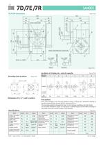
7D/7E/7R 7D/7E/7R Dimensions (Unit : mm) 230 130 50 48 40 65 50 48 40 STOP POSITION c d 130 65 S 35 65 T 165 20h6 (+0.000 ) -0.013 W T b a 25 195 70 25h6 ( +0.000 ) -0.013 S U 150 18 40 90h8 (+0.000 ) -0.054 50 200 7N9 ( +0.000 ) -0.036 15 4 100 M10x1.5, 15DP. 7N9 ( +0.000) -0.036 4 R 20h6 (+0.000 ) -0.013 15 INDEX REFERENCE POSITION INPUT V 25h6 (+0.000 ) -0.013 60 V R OUTPUT Figure 7D-1 Locations of oil plug, etc., and oil capacity Mounting hole locations Figure 7D-2 Mounting position 1 2 Figure 7D-3 3 4 5 6 85 M10x1.5, 15DP. 100 95 65 R T Location 97 65 22 0 S 0 35 65 100 S 65 95 65 97 0 35...
Open the catalog to page 13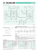
8D/8E/8R 8D/8E/8R Dimensions (Unit : mm) 280 60 232 160 60 57 47 80 57 57 175 47 170 47 STOP POSITION 82 S c U W 35 V d b T a T 30 V 7N9 ( +0.000 ) -0.036 120 20 4 M10x1.5, 20DP. 10N9 (+0.000 ) -0.036 INPUT 30h6 ( +0.000 ) -0.013 R 5 15 75 INDEX REFERENCE POSITION 25h6 (+0.000 ) -0.013 25h6 (+0.000 ) -0.013 80 200 235 80 30h6 ( +0.000 ) -0.013 S R 130 20 OUTPUT Figure 8D-1 Locations of oil plug, etc., and oil capacity Mounting hole locations Figure 8D-2 Mounting position 1 2 Figure 8D-3 3 4 5 6 114 M10x1.5, 20DP 80 115 40 130 125 R R Location 20 80 120 Output Input 20 Oil capacity( ) 80 25 0...
Open the catalog to page 15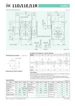
11D/11E/11R 11D/11E/11R Dimensions (Unit : mm) 314 64 270 186 64 54 93 58 54 212 48 208 101 STOP POSITION T U 3 V S V 35h6 (+0.000 ) -0.016 W 50 (ECCENTRIC CAPACITY 3mm) d 35 T b a R M10x1.5, 20DP. 140 5 10N9 (+0.000 ) -0.036 23 5 35h6 (+0.000 ) -0.016 24 89 INDEX REFERENCE POSITION 30h6 (+0.000 ) -0.013 110 c 245 30h6 (+0.000) -0.013 292 93 S R 10N9 (+0.000 ) -0.036 INPUT 160 24 OUTPUT Figure 11D-1 Locations of oil plug, etc., and oil capacity Mounting hole locations Figure 11D-2 Mounting position 1 2 Figure 11D-3 3 4 5 6 126 M10x1.5, 20DP. 93 148 66 0 53 95 113 25 168 0 104 Location 160 R R...
Open the catalog to page 17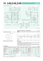
14D/14E/14R 14D/14E/14R Dimensions (Unit : mm) 396 338 220 84 88 110 69 80 84 122 45h6 (+0.000) -0.016 d S V T T b U a W 45 40h6 ( +0.000) -0.016 320 140 110 S 370 250 69 STOP POSITION c 258 65 60 88 V 20 12N9 (+0.000) -0.043 INPUT 45h6 (+0.000 ) -0.016 180 5 M12x1.75, 25DP. 12N9 ( +0.000 ) -0.043 5 R 40h6 ( +0.000 ) -0.016 30 120 INDEX REFERENCE POSITION R 210 20 OUTPUT Figure 14D-1 Locations of oil plug, etc., and oil capacity Mounting position Figure 14D-2 2 3 110 Mounting hole locations 1 Figure 14D-3 4 5 180 6 M12x1.75, 25DP. 150 70 Location 210 R R 110 Output Input 20 180 20 Oil capacity(...
Open the catalog to page 19All Sankyo America catalogs and technical brochures
 The Zero-Backlash Technology
32 Pages
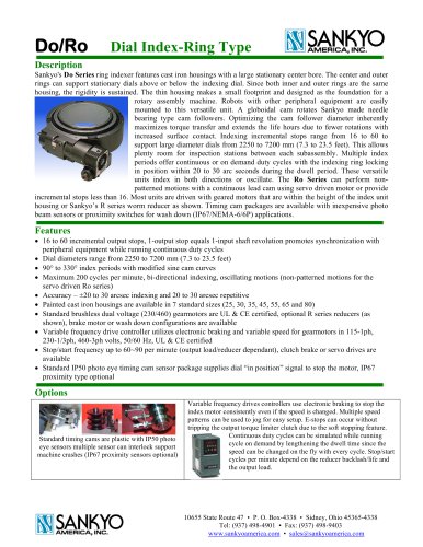 Do Series, Ring Indexer
4 Pages
 Coil Feeds for Presses
23 Pages
 RE Series Catalog
20 Pages
 RA Series Catalog
22 Pages
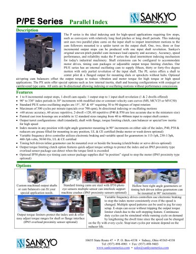 P Series Catalog
2 Pages
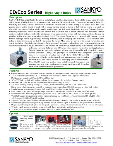 ED Series Catalog
1 Page
 DT/RT/DTR Series Catalog
5 Pages
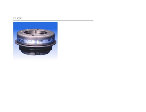 TC Series Catalog
11 Pages
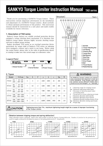 TAD Alpha Catalog
2 Pages
 GY Series Catalog
20 Pages


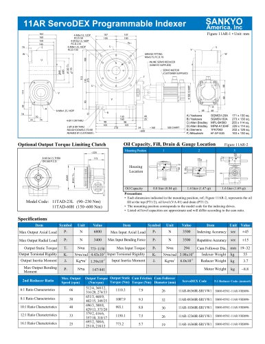

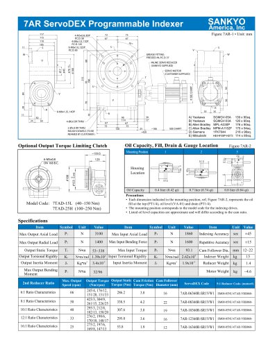
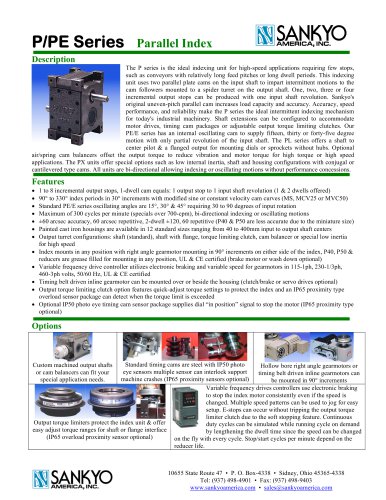


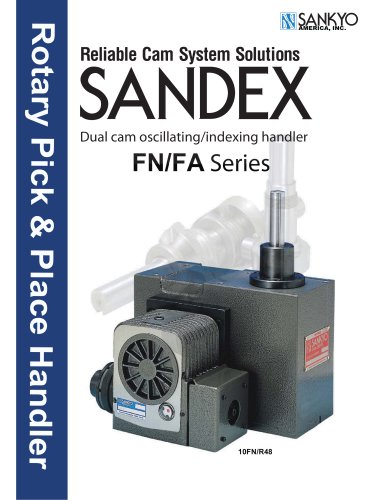
Archived catalogs
 Eco Series ED Catalog
32 Pages
 Alpha Series Catalog
25 Pages
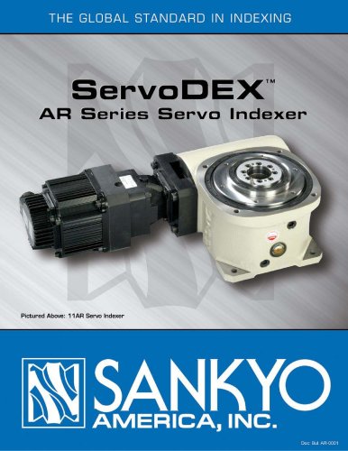 Alpha Servo Catalog
18 Pages
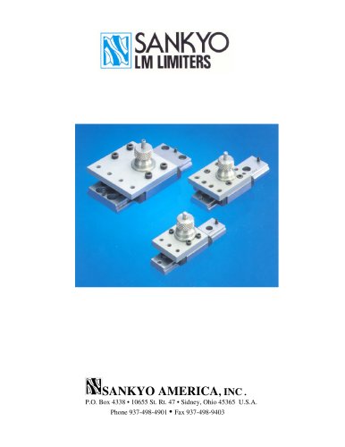 LM Series Catalog
8 Pages
 DF, EF & RF Series Catalog
19 Pages
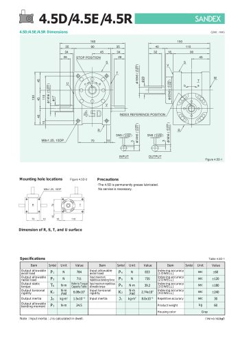 D, E & R Series Catalog
18 Pages
- Rail conveyor
- Transport rail conveyor
- Horizontal conveyor
- Feeder
- Turntable
- Chain conveyor
- Electric rotary table
- Horizontal rotary table
- Motor-driven rotary table
- Mounting machine
- Automatic assembling machine
- Tool changer
- Index unit
- Vertical rotary table
- Machine tool rotary table
- Cam indexer
- Rotary indexer
- CNC rotary table
- Assembly machine for industrial applications