- Catalogs
- Sankyo America
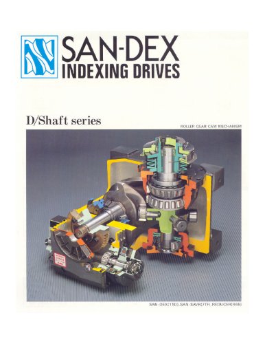
- D, E & R Series Catalog
D, E & R Series Catalog
D, E & R Series Catalog
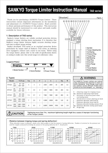
Models 11D, 11E, and 11R are compatible with reducers R65 and R80, and torque limiters 7TF, 8TF, 11TF, 7TC, 8TC, and 11TC. Models 14D, 14E, and 14R can use reducers R65, R80, and R100, and torque limiters 8TF, 11TF, 14TF, 8TC, 11TC, and 14TC. Models 17D, 17E, and 17R are compatible with reducers R80 and R100, and torque limiters 11TF, 14TF, 11TC, and 14TC. Models 18D and 18R can use reducers R80, R100, and R125, and torque limiters 11TF, 14TF, 18TF, 11TC, 14TC, and 18TC. All components require a collar for mounting.
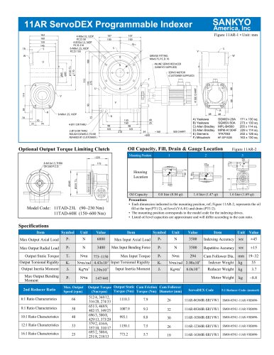
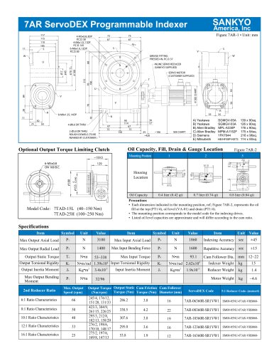
Reducers can be mounted in 16 different positions, each with an oil plug, oil level, and drain. Oil levels depend on the cam profile and number of cam followers. Mounting positions are coded for indexing, oscillating, and roller drives.
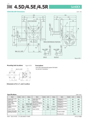
Key specifications include output and input allowable axial load, indexing accuracy, repetitive accuracy, product weight, housing color, input maximum repetitious bending force, input maximum repetitious allowable torque, output allowable radial load, output static torque, output torsional rigidity, input torsional rigidity, output inertia, input inertia, and output allowable bending moment. Detailed values are available in the specifications tables for each model series (14D/14E/14R, 17D/17E/17R, 18D/18R).
Example model codes are provided to illustrate the configuration of indexing drives, reducers, and torque limiters.
Catalog excerpts

Each point indicated in the mounting positions shown in Figure 8D-3 represents (starting at top) the oil plug (PT1/2), oil level (VA), and drain (PT1/2).The mounting positions correspond to code i for the indexing, oscillating, and roller drives. The oil levels indicated in Figure 8D-3 are given in general figures and will differ according to the profile of the cam and the number of cam followers. Table 8D-1 Item Symbol UnitValueNm/radN2156 Item Symbol UnitValueItem Symbol UnitValue > Output allowableaxial loadInput allowableaxial loadIndexing accuracy(1 DWELL)Indexing accuracy(2 DWELL)Indexing...
Open the catalog to page 9
Each point indicated in the mounting positions shown in Figure 11D-3 represents (starting at top) the oil plug (PT1/2), oil level (VA), and drain (PT1/2).The mounting positions correspond to code i for the indexing, oscillating, and roller drives. The oil levels indicated in Figure 11D-3 are given in general figures and will differ according to the profile of the cam and the number of cam followers. Table 11D-1 Item Symbol UnitValueNm/radN4900 Item Symbol UnitValueItem Symbol UnitValue > Output allowableaxial loadInput allowableaxial loadIndexing accuracy(1 DWELL)Indexing accuracy(2 DWELL)Indexing...
Open the catalog to page 11
Each point indicated in the mounting positions shown in Figure 14D-3 represents (starting at top) the oil plug (PT1/2), oil level (VA), and drain (PT1/2).The mounting positions correspond to code i for the indexing, oscillating, and roller drives. The oil levels indicated in Figure 14D-3 are given in general figures and will differ according to the profile of the cam and the number of cam followers. Table 14D-1 Item Symbol UnitValueNm/radN7154 Item Symbol UnitValueItem Symbol UnitValue > Output allowableaxial loadInput allowableaxial loadIndexing accuracy(1 DWELL)Indexing accuracy(2 DWELL)Indexing...
Open the catalog to page 13
Each point indicated in the mounting positions shown in Figure 17D-3 represents (starting at top) the oil plug (PT3/4), oil level (VB), and drain (PT3/4).The mounting positions correspond to code i for the indexing, oscillating, and roller drives. The oil levels indicated in Figure 17D-3 are given in general figures and will differ according to the profile of the cam and the number of cam followers. Table 17D-1 Item Symbol UnitValueNm/radN8134 Item Symbol UnitValueItem Symbol UnitValue > Output allowableaxial loadInput allowableaxial loadIndexing accuracy(1 DWELL)Indexing accuracy(2 DWELL)Indexing...
Open the catalog to page 15All Sankyo America catalogs and technical brochures
 The Zero-Backlash Technology
32 Pages
 Do Series, Ring Indexer
4 Pages
 Coil Feeds for Presses
23 Pages
 RE Series Catalog
20 Pages
 RA Series Catalog
22 Pages
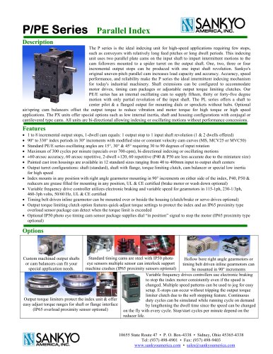 P Series Catalog
2 Pages
 D Series Catalog
24 Pages
 ED Series Catalog
1 Page
 DT/RT/DTR Series Catalog
5 Pages
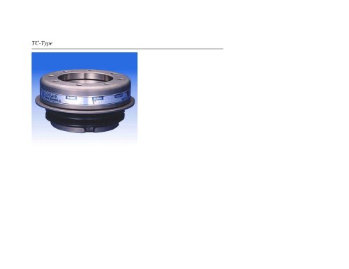 TC Series Catalog
11 Pages
 TAD Alpha Catalog
2 Pages
 GY Series Catalog
20 Pages


Archived catalogs
 Eco Series ED Catalog
32 Pages
 Alpha Series Catalog
25 Pages
 Alpha Servo Catalog
18 Pages
 LM Series Catalog
8 Pages
 DF, EF & RF Series Catalog
19 Pages
- Rail conveyor
- Transport rail conveyor
- Horizontal conveyor
- Feeder
- Turntable
- Chain conveyor
- Electric rotary table
- Horizontal rotary table
- Motor-driven rotary table
- Mounting machine
- Automatic assembling machine
- Tool changer
- Index unit
- Vertical rotary table
- Machine tool rotary table
- Cam indexer
- Rotary indexer
- CNC rotary table
- Assembly machine for industrial applications