- Catalogs
- Sankyo America
- Alpha Series Catalog
Alpha Series Catalog

Alpha Series Catalog
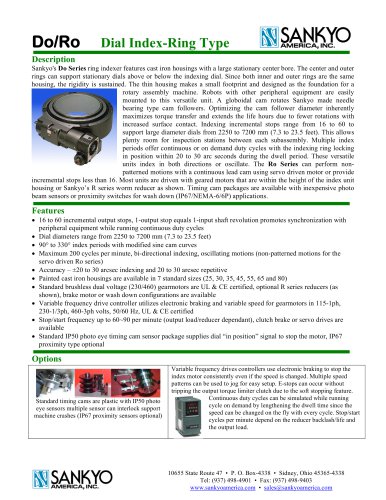
Sankyo's AD/Alpha Series Dial Index is designed for robust motion control with a low-profile design and cast iron housing. It features a stationary hollow dial for routing air lines and wiring, and a globoidal cam with needle bearing cam followers for optimized torque transfer and extended lifespan. The units support continuous or on-demand duty cycles with high accuracy and reliability.
The series includes models 7AD to 45AD, with dial diameters from 560mm to 3600mm. It offers 2 to 32 incremental output stops and index periods from 120° to 330°. The units support bi-directional indexing and oscillating motions, with a maximum of 200 cycles per minute. Index accuracy is within ±30 arc seconds, with repetitive accuracy at 30 arc seconds.
Equipped with brushless dual voltage gearmotors, variable frequency drive controllers, and optional torque limiting clutches, the units can be mounted in any position with right-angle gearmotor mounting options. They are compatible with wash-down applications and offer explosion-proof options.
Custom machined output flanges, timing cam sensor packages, and variable frequency drives are available. The units can be equipped with output torque limiters and stationary risers for additional mounting needs.
The AD/Alpha Series is suitable for applications requiring precise indexing and motion control, with programmable stops and speeds. It is ideal for environments where reliability and flexibility are critical, such as manufacturing and automation processes.
Sankyo's AD/Alpha Series Dial Index provides a versatile and reliable solution for motion control, with a range of options to suit various industrial applications. Its robust design and advanced features ensure optimal performance and longevity.
The document discusses the use of sensors and controllers to optimize machine cycle times, highlighting environmental compatibility. Standard photo eye sensors are IP50 rated, while most proximity sensors are IP67 rated. Alkaline coolants with a PH10 can cause corrosion, and explosion-proof sensors are available.
Variable Frequency Drive (VFD) controllers are used for stopping indexing units, offering maintenance-free operation and preventing brake dust contamination. They support frequent stop/start cycles, multi-patterned speed ramps, electronic braking, and motor protection. A braking resistor is needed in high voltage applications to dissipate heat.
Sankyo offers repair or rebuild services at their facility in Sidney, Ohio, and on-site services across various regions including North America, Central America, South America, Europe, the Middle East, Africa, Asia, and Australia.
Consult Sankyo sales representatives for sizing index units and recommending options. Check specifications and dimensions with Sankyo sales before ordering, as they are subject to change.
Tables and figures detail dimensions, specifications, and model codes for components such as torque limiters and timing cams. Correctly specifying product codes is emphasized to ensure compatibility with applications.
Catalog excerpts

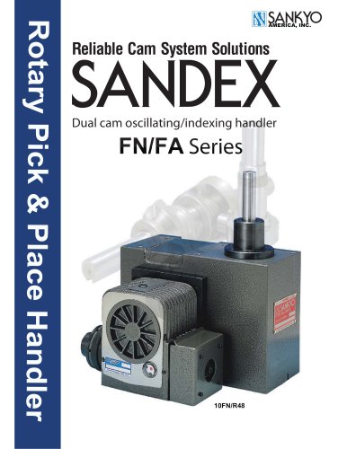
Optimum Reliability in Motion Control Units INDEXING DRIVES
Open the catalog to page 1
AD Alpha Series Dial Index Description Sankyo's AD/Alpha Series features a low profile design cast iron housing with a ground pilot flange for mounting dial plates, hub less gears, or weldment fixtures. Above the indexing dial, a second dial mounting surface is stationary and hollow to allow air lines, wiring or bearings for a shaft to be routed through the tolerance bore. A globoidal cam rotates Sankyo made needle bearing type cam followers. Optimizing the cam follower diameter inherently maximizes torque transfer and extends the life hours due to fewer rotations with increased surface contact....
Open the catalog to page 2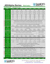
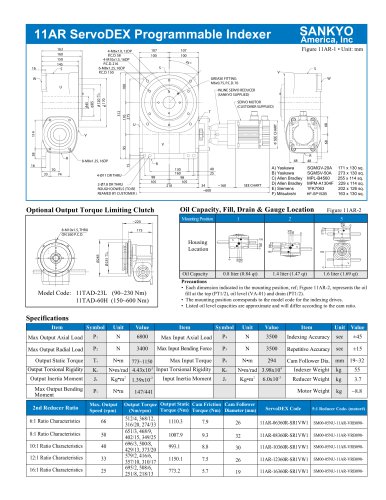
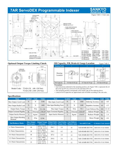
AD/Alpha Series Specifications Model Dial Diameter mm (inch) Dial Pilot Bore mm (inch) Hollow Bore Dia. mm (inch) Max. Axial Load N (lb) Max. Radial Load kg (lb) Shaft Center Dist. mm (in) INDEX HOUSING Output Type Indexing Stops Oscillating Motion Angle Index Period Output Bending Moment Input Input Speed Input Bending Moment Index Accuracy Index Accuracy Quick Reference Chart 7AD 9AD 11AD REDUCER / MOTOR Gearmotor (standard) Gearmotor Power Gearmotor Weight C-face Reducer Clutch-brake Wash-down Explosion Proof Motors OPTIONS Output Clutch Torque Limiter Torque Capacity N-m (in-lb) Torque Limiter...
Open the catalog to page 3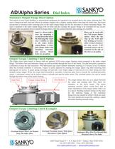
AD/Alpha Series Dial Index Stationary Output Flange Riser Option This option is used if part handlers or measurement equipment are required to be mounted above the rotary indexing dial. The riser is flanged on both ends and offered in multiple lengths with a slightly smaller hollow bore than the index bore. Each riser incorporates a tolerance male centering pilot on the index output flange and for the dial plate or fixture mounting flange. The riser is mounted to the index output flange with (4) bolts and also includes the grease fitting to be extended for easy access. Standard units are painted...
Open the catalog to page 4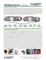
AD/Alpha Series Dial Index Gearmotor Drive Mounting All of our Alpha index units have two gearmotor sizes. On some models, the input shaft diameter also changes with each motor size. The smaller motors are usually within the height of the index and no mounting interference occurs with the bottom of the dial or the housing mounting feet. The output clutch also serves as a spacer to enhance dial clearance. If the TAD output torque limiting clutch is not used, interference may occur with the bottom of the dial in the standard mounting position-1 as shown below. As an option, the gearmotor package...
Open the catalog to page 5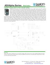
Dial Index Variable Frequency Drive (VFD) Controller Option Stopping indexing units can be accomplished many different ways. Sankyo chooses the VFD controllers because they are maintenance free and no residual brake dust contamination. Some advantages of using this type of controller are frequent stop/starting cycles, multi patterned speed ramps, electronic braking, varying speed on the fly and motor protection. Preset speeds for jog setup or emergency stop recovery are valuable to minimize damage to the machine tooling and indexing unit. Brake motors can be used in conjunction with the VFD to...
Open the catalog to page 6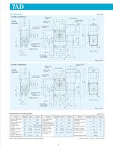
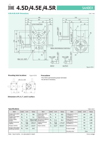
FIXED FLANGE STOP POSITION GREASE FITTING - INDEX REFERENCE (SCRIBED LINE) FIXED FLANGE GREASE FITTING - GEARED MOTOR INDEX REFERENCE (SCRIBED LINE) Specifications of indexing drive Note: Input mass moment of inertia J is calculated in dwell. Unit conversion: (in.-lbs.) = (N-m) X 8.851
Open the catalog to page 7
Specifications of geared motor Note: Other reducers and gear ratios are available. Mounting interference may occur. Contact Sankyo Sales for specific details. Torque limiter mounting specifications (optional) Figure 7AD-3 Timing cam-Photo switch (optional) Index Dial Example Model Code Indexing Drive Torque Limiter Sensor Model (OMRON) Connector Model Note: Timing cam shown is for a 270° index period and a 90° dwell. Example Model Code Timing Cam-Photo Switch TC - [T] - 7AD •The dimension drawing(Figure 7AD-1, 7AD-2) shows mounting position 1 for the geared motor. •Model 7AD can be equipped with...
Open the catalog to page 8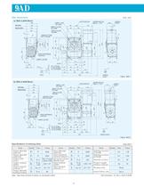
FIXED FLANGE STOP POSITION GEARED MOTOR FIXED FLANGE STOP POSITION GEARED MOTOR HANDLE SHAFT Specifications of indexing drive Table 9AD-1 Note: Input mass moment of inertia J is calculated in dwell. Unit conversion: (in.-lbs.) = (N-m) X 8.851
Open the catalog to page 9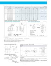
Specifications of geared motor Note: Other reducers and gear ratios are available. Mounting interference may occur. Contact Sankyo Sales for specific details. Torque limiter mounting specifications (optional) Figure 9AD_3 Timing cam-Photo switch (optional) Index Dial Example Model Code Indexing Drive Torque Limiter Sensor Model (OMRON) Connector Model Example Model Code Timing Cam-Photo Switch TC - pT] •The dimension drawing (Figure 9AD-1, 9AD-2) shows mounting position 1 for the geared motor. •Model 9AD can be equipped with 0.2kW or 0.4kW motor. When using the 0.4kW motor, the motor will protrude...
Open the catalog to page 10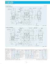
FIXED FLANGE HANDLE SHAFT FIXED FLANGE STOP POSITION GEARED MOTOR HANDLE SHAFT Specifications of indexing drive Table 11AD-1 Note: Input mass moment of inertia J is calculated in dwell. Unit conversion: (in.-lbs.) = (N-m) X 8.851
Open the catalog to page 11
Specifications of geared motor Note: Other reducers and gear ratios are available. Mounting interference may occur. Contact Sankyo Sales for specific details. Torque limiter mounting specifications (optional) Figure ^ 1AD_3 Timing cam-Photo switch (optional) Index Dial Example Model Code Torque Limiter Sensor Model (OMRON) Connector Model Example Model Code Timing Cam-Photo Switch •The dimension drawing(Figure 11AD-1,11AD-2) shows mounting position 1 for the geared motor. •Model 11 AD can be equipped with 0.4kW or 0.75kW motor. Exchange is not permitted after purchase because of different hollow...
Open the catalog to page 12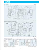
(a) Index With 0.75kW Motor & 5-50:1 Ratio Reducer,60~200:1 Ratios are Noted in Parenthesis (xx) GEARED MOTOR HANDLE SHAFT (b) Index With 1.5kW Motor & 5-80:1 Ratio Reducer FIXED FLANGE STOP POSITION GEARED MOTOR Specifications of indexing drive Table 15AD-1 Note: Input mass moment of inertia J is calculated in dwell. Unit conversion: (in.-lbs.) = (N-m) X 8.851
Open the catalog to page 13All Sankyo America catalogs and technical brochures
 The Zero-Backlash Technology
32 Pages
 Do Series, Ring Indexer
4 Pages
 Coil Feeds for Presses
23 Pages
 RE Series Catalog
20 Pages
 RA Series Catalog
22 Pages
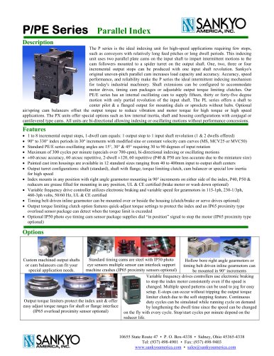 P Series Catalog
2 Pages
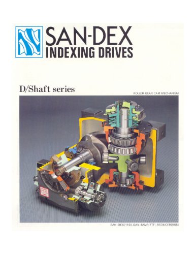 D Series Catalog
24 Pages
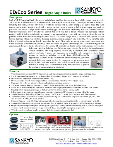 ED Series Catalog
1 Page
 DT/RT/DTR Series Catalog
5 Pages
 TC Series Catalog
11 Pages
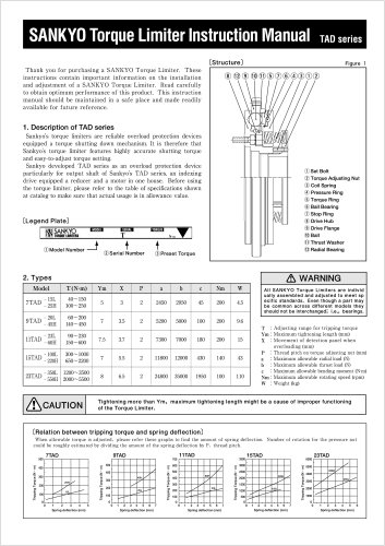 TAD Alpha Catalog
2 Pages
 GY Series Catalog
20 Pages


Archived catalogs
 Eco Series ED Catalog
32 Pages
 Alpha Servo Catalog
18 Pages
 LM Series Catalog
8 Pages
 DF, EF & RF Series Catalog
19 Pages
 D, E & R Series Catalog
18 Pages
- Rail conveyor
- Transport rail conveyor
- Horizontal conveyor
- Feeder
- Turntable
- Chain conveyor
- Electric rotary table
- Horizontal rotary table
- Motor-driven rotary table
- Mounting machine
- Automatic assembling machine
- Tool changer
- Index unit
- Vertical rotary table
- Machine tool rotary table
- Cam indexer
- Rotary indexer
- CNC rotary table
- Assembly machine for industrial applications