


- Company
- Products
- Catalogs
- News & Trends
- Exhibitions
Type 41-23 Universal Pressure Reducing Valve

Type 41-23 Universal Pressure Reducing Valve
Catalog excerpts
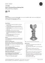
T 2512 EN Type 41-23 Universal Pressure Reducing Valve Self-operated Pressure Regulators Application Pressure regulators for set points from 0.05 to 28 bar · Valve nominal sizes DN 15 to 100 · Nominal pressure PN 16 to 40 Suitable for liquids, gases and vapors up to 350 °C The valve closes when the downstream pressure rises. Special features •• Low-maintenance proportional regulators requiring no auxiliary energy •• Frictionless plug stem seal with stainless steel bellows •• Control line kit available for tapping the pressure directly at the valve body •• Wide set point range and convenient set point adjustment using a nut •• Exchangeable actuator and set point springs •• Spring-loaded, single-seated valve with upstream and downstream pressure balancing 1) by a stainless steel bellows •• Soft-seated plug for high shut-off requirements •• Low-noise standard plug •• All wetted parts free of non-ferrous metal Versions Pressure reducing valve to regulate the downstream pressure p2 to the adjusted set point. The valve closes when the downstream pressure rises. Type 41-23 · Standard version Type 2412 Valve · Valve DN 15 to 100 · Metal-seated plug Body made of cast iron EN-GJL-250, spheroidal graphite iron EN-GJS-400-18-LT, cast steel 1.0619, forged steel or CrNiMo steel 1.4408 Type 2413 Actuator with EPDM rolling diaphragm Version with additional features Pressure reducing valve for low flow rates Valve with micro-flow trim (KVS = 0.001 to 0.04) or special KVS coefficients (restricted cross-sectional area of flow) Steam pressure reducing valve With compensation chamber for steam up to 350 °C Pressure reducing valve with increased safety Actuator with leakage line connection and seal or two diaphragms and diaphragm rupture indicator 1) With KVS ≤ 2.5: without balancing bellows Fig. 1: Type 41-23 Universal Pressure Reducing Valve Special versions –– Control line kit for tapping the pressure directly at the valve body (accessories) –– With internal parts made of FKM, e.g. for use with mineral oils –– EPDM diaphragm with PTFE protective facing –– Actuator for remote set point adjustment (autoclave control) –– Bellows actuator for valves in DN 15 to 100 · Set point ranges 2 to 6, 5 to 10, 10 to 22 or 20 to 28 bar –– Valve with flow divider ST 1 or ST 3 (DN 65 to 100) for particularly low-noise operation with gases and vapors (see Data Sheet u T 8081) –– Version entirely of stainless steel SAMSON AKTIENGESELLSCHAFT · Weismüllerstraße 3 · 60314 Frankfurt am Main, Germany Phone:
Open the catalog to page 1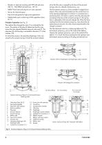
- Stainless Cr steel seat and plug with PTFE soft seal (max. 220 °C) • With EPDM soft seal (max. 150 °C) - Stellite®-faced seat and plug for low-wear operation - Version for industrial gases - Free of oil and grease for high-purity applications - Wetted plastic parts conforming to FDA regulations (max. 60 °C) Principle of operation (see Fig. 2) The medium flows through the valve (1) as indicated by the arrow. The position of the plug (3) determines the flow rate across the area released between plug and valve seat (2). The plug stem (5) with the plug is connected to the stem (11) of the actuator...
Open the catalog to page 2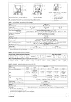
Valve for small flow rates KVS ≤ 2.5: without balancing bellows 2 Plug with metal sealing, with flow divider ST 1 3.1 Plug with metal sealing Plug with soft sealing 3.2 Plug with soft sealing Fig. 3: Additional features for Type 41-23 Universal Pressure Reducing Valve Table 1: Technical data · All pressures in bar (gauge) Valve Nominal pressure Nominal size Max. perm. differential pressure ∆p Max. permissible temperature Valve plug See pressure-temperature diagram in u T 2500 Metal seal: 350 °C · PTFE soft seal: 220 °C · EPDM or FKM soft seal: 150 °C · NBR soft seal: 80 °C Metal seal: Leakage...
Open the catalog to page 3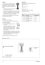
Installation Normally, the valve is installed with the actuator suspended downwards. Install pipelines horizontally with a slight downward slope on both sides of the valve for drainage of the condensate. - The direction of flow must correspond with the arrow on the valve body. - The control line must be adapted to match the onsite conditions and is not delivered with the valve. On customer request, a control line kit for pressure tapping directly at the valve body (see Accessories) is available. For further details on installation, refer to Mounting and Operating Instructions ► EB 2512. Accessories...
Open the catalog to page 4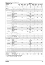
Table 5: Dimensions in mm and weights in kg Pressure reducing valve Nominal size 335 Other materials Forged steel Standard version with Type 2413 Actuator with rolling diaphragm Height H 0.05 to 0.25 bar Valve spring force F Valve spring force F Valve spring force F Valve spring force F Actuator Valve spring force F Valve spring force F 0.1 to 0.6 bar Valve spring force F Weight for version with actuator with rolling diaphragm 0.05 to 0.6 bar 0.2 to 2.5 bar 2 to 16 bar Weight, based on cast iron 1), approx. kg Version with Type 2413 Actuator with bellows Height H 2 to 6 bar Valve spring force...
Open the catalog to page 5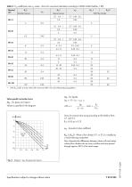
Table 6: KVS coefficients and xFZ values · Terms for noise level calculation according to VDMA 24422 (edition 1.89) Nominal size Standard version With flow divider With KVS 0.001 to 0.04: Valve with micro-trim (DN 15 to 25) without balancing bellows Valve-specific correction terms ΔLG · For gases and vapors: Values as specified in the diagram Terms for control valve sizing according to IEC 60534, Parts 2-1 and 2-2: xFZ · Acoustical valve coefficient KVS 1, KVS 3 · When a flow divider ST 1 or ST 3 is installed as a noise-reducing component Flow characteristic differences between valves with and...
Open the catalog to page 6All SAMSON catalogs and technical brochures
 TROVIS 5590 Web Module
2 Pages
 Room Controller TROVIS 5572
2 Pages
 Room Panel TROVIS 5570
2 Pages
 Line Splitter TROVIS 5486
2 Pages
 Type 9 Temperature Regulator
6 Pages
 Type 8 Temperature Regulator
6 Pages
 Type 5 D Boiler Controller
2 Pages
 Rotary Plug Valve Type 62.7
7 Pages
 Actuator Type S
3 Pages
 Actuator Type MZ
4 Pages
 Actuator Type MN
3 Pages
 Actuator Type MD
3 Pages
 Actuator Type R
3 Pages
 Actuator Type AT
4 Pages
 Rotary Plug Valve Type 82.7
7 Pages
 Rotary Plug Valve Type 73.7
7 Pages
 Rotary Plug Valve Type 73.3
7 Pages
 Rotary Plug Valve Type 72.4
7 Pages
 Rotary Plug Valve Type 72.3
8 Pages
 SAMSON Positioners
28 Pages













Archived catalogs
 T21 11
6 Pages




- SAMSON stainless steel valve
- Water valve
- Ball valve
- SAMSON pneumatic valve
- Threaded valve
- Electrically operated valve
- SAMSON regulating valve
- SAMSON flange valve
- On/off valve
- Electric valve
- Gas solenoid valve
- Process software
- Directional control valve
- Gas valve
- Direct-operated solenoid valve
- Pneumatically-operated valve
- Terminal box
- Single-stage pressure regulator