- Company
- Products
- Catalogs
- News & Trends
- Exhibitions
Type 2 N and Type 2 NI Strainers with flanged connections
1 /4Pages

Type 2 N and Type 2 NI Strainers with flanged connections
1 /4Pages
Catalog excerpts
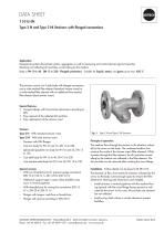
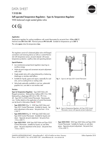
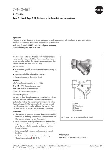
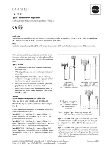
T 1015 EN Type 2 N and Type 2 NI Strainers with flanged connections Application Designed to protect downstream plants, aggregates as well as measuring and control devices against impurities Straining and collecting dirt particles carried along by the medium. Body in PN 10 to 40 · DN 15 to 250 · Flanged connections · Suitable for liquids, steam, and gases up to max. 450 °C The strainers consist of a Y-style body with flanged connections and a wide-meshed filter element (standard strainer insert) or a wide-meshed filter element with an additional fine-meshed filter element (dual strainer insert). Special features •• Compact design with face-to-face dimensions according to DIN •• Easy removal of the collected dirt particles •• Easy replacement of the strainer insert Versions Type 2 N · With standard strainer insert Type 2 NI · With dual strainer insert –– Strainers with DIN flanges –– Cast iron body for PN 10 and 16, DN 15 to 250 –– Spheroidal graphite iron body for PN 16 and 25, DN 15 to 150 –– Cast steel body for PN 16 to 40, DN 15 to 250 –– Cast stainless steel body for PN 16 to 40, DN 15 to 100 Special versions –– With two threaded ports for pressure gauge connection (DN 15 to 100: G ¼, DN 125 to 250: G ½) –– Additional support cage in cases where backflow may occur in vertical pipelines –– With threaded port for rinsing line connection (DN 15: G ¼, DN 20 to 250: G ½) –– Flanges with tongue, male face or female face –– Flanges with groove according to DIN 2512 Fig. 1: Type 2 N and Type 2 NI Strainers Principle of operation The medium flows through the strainer in the direction indicated by the arrow on the body. The uncleaned medium first contacts the inside of the strainer insert (filter element). While it passes through the filter element, the dirt particles carried along by the medium are collected in the filter element. The dirt particles can be removed after undoing the cover flange. Installation · Further details can be found in u EB 1015 The direction of flow must match the direction indicated by the arrow on the body. Leave enough space to remove the filter element for cleaning (see Dimensions and weights). –– Install strainers in vertical pipelines with the medium flowing upward with the cover flange facing upward as indicated by the arrow. In this case, dirt particles are retained but not collected. –– Install swing check valves or similar devices to prevent backflow. SAMSON AKTIENGESELLSCHAFT · Weismüllerstraße 3 · 60314 Frankfurt
Open the catalog to page 1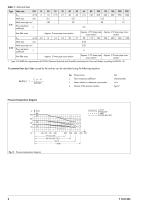
Table 1: Technical data Type 2 NI fulfills the requirements of DVGW (German Technical and Scientific Association for Gas Ap Pressure loss Z Flow resistance coefficient Pressure-temperature diagram
Open the catalog to page 2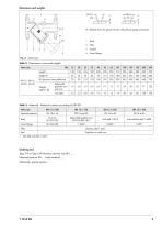
"X" detailed views for special version with pressure gauge connection 1 Body 2 Filter 3 Gasket 4 Cover flange Table 2: Dimensions in mm and weights Ordering text Type 2 N or Type 2 NI Strainer, nominal size DN ..., Nominal pressure PN body material ..., Optionally, special version ...
Open the catalog to page 3
Specifications subject to change without notice
Open the catalog to page 4All SAMSON catalogs and technical brochures
 TROVIS 5590 Web Module
2 Pages
 Room Controller TROVIS 5572
2 Pages
 Room Panel TROVIS 5570
2 Pages
 Line Splitter TROVIS 5486
2 Pages
 Type 9 Temperature Regulator
6 Pages
 Type 8 Temperature Regulator
6 Pages
 Type 5 D Boiler Controller
2 Pages
 Rotary Plug Valve Type 62.7
7 Pages
 Actuator Type S
3 Pages
 Actuator Type MZ
4 Pages
 Actuator Type MN
3 Pages
 Actuator Type MD
3 Pages
 Actuator Type R
3 Pages
 Actuator Type AT
4 Pages
 Rotary Plug Valve Type 82.7
7 Pages
 Rotary Plug Valve Type 73.7
7 Pages
 Rotary Plug Valve Type 73.3
7 Pages
 Rotary Plug Valve Type 72.4
7 Pages
 Rotary Plug Valve Type 72.3
8 Pages
 SAMSON Positioners
28 Pages


Archived catalogs
 T21 11
6 Pages


- Rototherm stainless steel valve
- Rototherm water valve
- Rototherm ball valve
- Rototherm pneumatic valve
- Electrically operated valve
- Rototherm threaded valve
- Rototherm regulating valve
- Rototherm flange valve
- Rototherm shut-off valve
- Gas solenoid valve
- Rototherm electric valve
- Rototherm process software
- Direct-operated solenoid valve
- Rototherm pressure regulator
- Directional control valve
- Rototherm gas valve
- Rototherm pneumatically-operated valve
- Rototherm single-stage pressure regulator
- Terminal box