- Company
- Products
- Catalogs
- News & Trends
- Exhibitions
TROVIS 5575 Heating and District Heating Controller
1 /8Pages
TROVIS 5575 Heating and District Heating Controller
1 /8Pages
Catalog excerpts

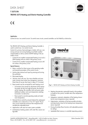
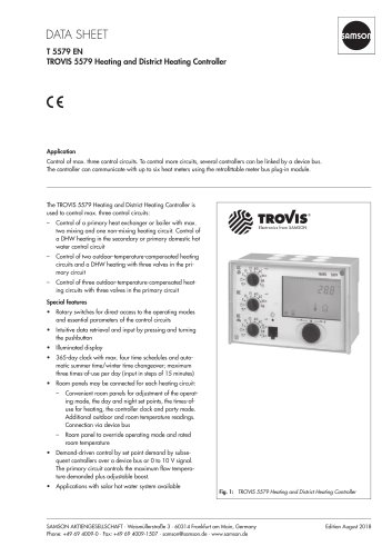
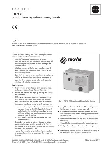
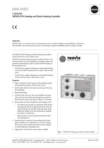
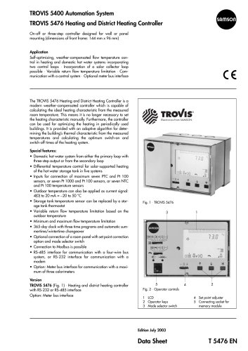
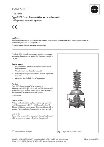
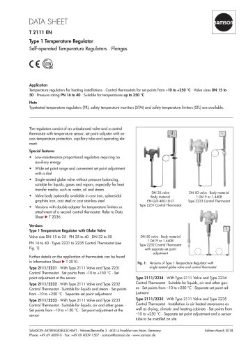
T 5575 EN TROVIS 5575 Heating and District Heating Controller Application Control of max. two control circuits. To control more circuits, several controllers can be linked by a device bus. The TROVIS 5575 Heating and District Heating Controller is used to control max. two control circuits: Control of a primary heat exchanger or boiler with max. one mixing and one non-mixing heating circuit (both weathercompensated) as well as control of DHW heating in the secondary circuit Electronics from SAMSON –– Control of one weather-compensated heating circuit and a DHW heating with two valves in the primary circuit –– Control of two weather-compensated heating circuits with two valves in the primary circuit Special features •• Rotary switches for direct access to the operating modes and essential parameters of the control circuits •• Intuitive data retrieval and input by pressing and turning the pushbutton •• Illuminated display •• 365-day clock with max. four time schedules and automatic summer time/winter time changeover; maximum three times-of-use per day (input in steps of 15 minutes) •• Room panels may be connected for each heating circuit: –– Convenient room panels for adjustment of the operating mode, the day and night set points, the times-ofuse for heating, the controller clock and party mode. Additional outdoor and room temperature readings. Connection via device bus –– Room panel to override operating mode and rated room temperature •• Demand-driven control by set point demand by subsequent controllers over a device bus or 0 to 10 V signal. The primary circuit controls the maximum flow temperature demanded plus adjustable boost. •• Applications with solar hot water system available •• Instantaneous heating systems with water flow sensor configurable Fig. 1: TROVIS 5575 Heating and District Heating Controller •• Heating characteristics optionally based on the gradient or based on four points; variable return flow temperature limitation •• Adaptation: automatic adaptation of the heating characteristic (room temperature sensor required) •• Optimization: calculation of the best possible activation and deactivation times for the heating (room temperature sensor required) •• Drying of jointless floors function with adjustable parameter settings •• Updatable flash memory in controller (operating system) SAMSON AKTIENGESELLSCHAFT · Weismüllerstraße 3 · 60314 Frankfurt am Main, Germany Phone: +49 69 4009-0 · Fax: +49
Open the catalog to page 1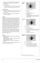
•• Configuration and parameterization either using memory module or online using USB converter 3 and TROVISVIEW software Operating modes •• Data logging function: –– Operating data can be saved to a data logging module –– Data can be displayed in the data log viewer on the PC Inputs and outputs Time-controlled operation •• 8 inputs for Pt 1000/Pt 100, PTC/Pt 100, NTC/Pt 100, Ni 1000/Pt 100 or Pt 500/Pt 100 temperature sensors and two binary inputs Day mode Night mode Control operation deactivated, frost protection only •• Three-step or on/off control circuit outputs configurable with PI control...
Open the catalog to page 2
* For systems with one control circuit, a maximum of four pumps are ava ilable
Open the catalog to page 3
Electrical connection and installation The controller consists of the housing containing the electronics and a separate terminal board for electrical connection. Two wires of max. 1.5 mm² may be connected to each terminal. The sensor connection lines must be installed separately from the lines carrying the power supply. For wall mounting, screw the terminal board to the wall. After wiring the controller, place the controller housing onto the terminal board and fasten it with two screws. Two fastening elements for panel mounting are included. 144 Ordering text TROVIS 5575-00xx Heating and District...
Open the catalog to page 4
Terminal assignment CAUTION! Never connect terminals 12 (ground for sensor) and 13 (ground for 0 to 10 V/0 to 20 mA)! 1) A 50 Ω resistor is required between terminals 03 and 13 for applying a 20 mA signal. Fig. 5: Terminal assignment of TROVIS 5575-000x and TROVIS 5575-002x Controllers CAUTION! Never connect terminals 12 (ground for sensor) and 13 (ground for 0 to 10 V/0 to 20 mA)! 1) A 50 Ω resistor is required between terminals 03 and 13 for applying a 20 mA signal. Fig. 6: Terminal assignment of TROVIS 5575-001x Controller
Open the catalog to page 5
Terminal assignment (continued) CAUTION! Never connect terminals 12 (ground for sensor) and 13 (ground for 0 to 10 V/0 to 20 mA)! 1) A 50 Ω resistor is required between terminals 03 and 13 for applying a 20 mA signal. Fig. 7: Terminal assignment of TROVIS 5575-000x and TROVIS 5575-002x Controllers with high base CAUTION! Never connect terminals 12 (ground for sensor) and 13 (ground for 0 to 10 V/0 to 20 mA)! 1) A 50 Ω resistor is required between terminals 03 and 13 for applying a 20 mA signal. Fig. 8: Terminal assignment of TROVIS 5575-001x Controller with high base
Open the catalog to page 6
Specifications subject to change without notice
Open the catalog to page 8All SAMSON catalogs and technical brochures
 TROVIS 5590 Web Module
2 Pages
 Room Controller TROVIS 5572
2 Pages
 Room Panel TROVIS 5570
2 Pages
 Line Splitter TROVIS 5486
2 Pages
 Type 9 Temperature Regulator
6 Pages
 Type 8 Temperature Regulator
6 Pages
 Type 5 D Boiler Controller
2 Pages
 Rotary Plug Valve Type 62.7
7 Pages
 Actuator Type S
3 Pages
 Actuator Type MZ
4 Pages
 Actuator Type MN
3 Pages
 Actuator Type MD
3 Pages
 Actuator Type R
3 Pages
 Actuator Type AT
4 Pages
 Rotary Plug Valve Type 82.7
7 Pages
 Rotary Plug Valve Type 73.7
7 Pages
 Rotary Plug Valve Type 73.3
7 Pages
 Rotary Plug Valve Type 72.4
7 Pages
 Rotary Plug Valve Type 72.3
8 Pages
 SAMSON Positioners
28 Pages


Archived catalogs
 T21 11
6 Pages


- SAMSON stainless steel valve
- Water valve
- Ball valve
- SAMSON pneumatic valve
- Electrically operated valve
- Threaded valve
- SAMSON regulating valve
- SAMSON flange valve
- On/off valve
- Gas solenoid valve
- Electric valve
- Process software
- Direct-operated solenoid valve
- Gas valve
- Pressure limiter
- Directional control valve
- Pneumatically-operated valve
- Single-stage pressure regulator
- Terminal box