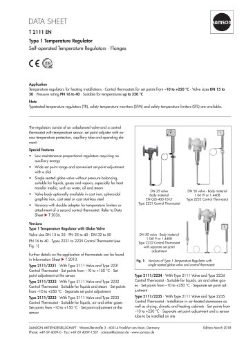
Catalog excerpts

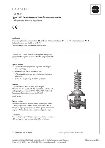
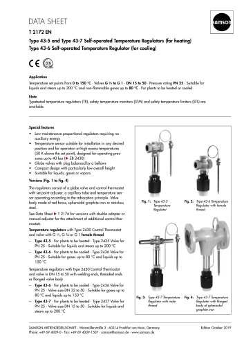
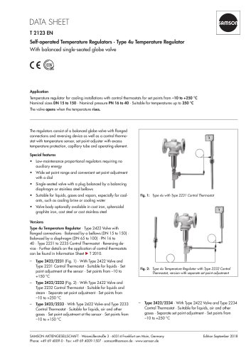
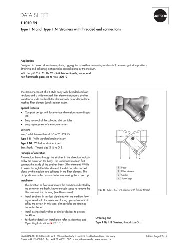
Application Temperature regulator with either mixing or flow-diverting valve for installations which are heated or cooled with liquids, with control thermostats for set points from -10 oC to +250 oC • Three-way valves in nominal sizes DN 15 to DN 100 • Nominal pressures PN 16 to PN 40 and temperatures up to 350 oC Conversion of valve sizing coefficients: Cv (in U.S.-gallons/min) = 1.17 • Kvs (in m3/h) Kvs (in m3/h) = 0.86 • Cv (in U.S.-gallons/min) Note Typetested temperature regulators (TR), temperature limiters (TL), safety temperature monitors (STM) and safety temperature limiters (STL) are available. The regulators consist of an unbalanced three-way valve and a control thermostat, comprising a temperature sensor, a set point adjustment head with an excess temperature safety device, a capillary tube and an operating element. Specifal features - Low-maintenance P-regulators requiring no auxiliary energy - Wide set point range and easy set point adjustment - Three-way valve, optionally with a plug arrangement for mixing or diverting of liquids - Flow rate across the is practically independent of the position of the valve plug - Valve body optionally made of cast iron, cast steel or stainless cast steel - Versions with double adapter are available for attachment of a temperature limiter or a second control thermostat. For details, see Data Sheet T 2036 E. Versions Temperature Regulator Type 8 • With Type 2118 Three-way Valve • DN 15 to DN 100 • PN 16 to PN 40 • Type 2231 to Type 2235 Control Thermostats. Three-way valves optionally with plug arrangement for mixing or flow-diverting service. The versions in sizes DN 15 to DN 25 are applicable for both mixing and flow-diverting services. For details on the application of the thermostats, see Information Sheet T 2010 E. Type 2118/2231 (Fig. 1) • With Type 2231 Control Thermostat • For liquids and steam • Set points from -10 to +150 °C • Set point adjustment at the sensor. Type 2118/2232 (Fig. 2) • With Type 2232 Control Thermostat • For liquids • Set points from -10 to +250 °C • Separate set point adjustment. Type 2118/2233 • With Type 2233 Control Thermostat • For liquids, air and other gases • Set points from -10 to +150 °C • Set point adjustment at the sensor. Type 2118/2234 • With Type 2234 Control Thermostat • For liquids, air and other gases • Set points from -10 to +250 °C • Separate set point adjustment. Type 2118/2235 • With Type 2235 Control Thermostat • For air-heated storerooms, drying, climatic and heating cabinets • Set points from -10 to +250 °C • Separate set point adjustment and a sensor tube which can be installed by the user. ANSI version available on request. Pressure-Temperature Diagram The operating pressures specified are limited by the Pressure-Temperature Diagram. extension piece Associated Information Sheet Data Sheet
Open the catalog to page 1
Principle of operation (Figs. 3 and 4) The regulators operate according to the liquid expansion principle. The temperature sensor (11), capillary tube (8) and operating element (7) are filled with an expansion liquid. The temperature-dependent change in volume of this liquid causes the operating element to move and as a result also the plug stem (5) of the control valve with the attached plug (3). The position of the plug determines the flow rate of the heat transfer medium across the free area between the seat (2) and plug. The set point is adjustable with a key (9) to a value which can be...
Open the catalog to page 2
Tabelle 2 • Materials (WN = Material Number acc. to DIN) Typetetsted safety devices The register number is available on request. Available are: Temperature Regulators (TR) with a Type 2231,2232, 2233, 2234 or 2235 Control Thermostat and a Type 2118 Three-way Valve, in sizes DN 15 to DN 100, for which the maximum operating pressure should not exceed the maximum permissible differential pressure specified in the "Technical data". Sensor without thermowell: Applicable up to 40 bar. With thermowell: Only use SAMSON version, G1, of bronze and WN 1.4571 up to 40 bar, of copper up to 16 bar....
Open the catalog to page 3
Table 3 - Dimensions in mm and weights ^028(030) Threaded connection G1 for PN 40 (version of copper PN 16) G1 V4 for PN 63 Distance piece (Weight approx. 0.2 kg) Extension piece (Weight approx. 0.5 kg) Flanges DN 32 for PN 40 DN 40 for PN 100 Dimensions in parentheses () □ □□□□[ □ □ □ □ □ D\ □□□□□□[ □□□□□□□□a □□□□□□□□a □□□□□□□□a Flange for Type 2233 and Type 2234 Flange PN 6; 140 external 0 Flange PN 40/DN 32 Dimensions in parentheses () G1 Distance piece: L = 55 mm Extension piece L = 140 mm Specifications subject to change without notice. SAMSON AG - MESS- UND REGELTECHNIK...
Open the catalog to page 4All SAMSON catalogs and technical brochures
-
TROVIS 5590 Web Module
2 Pages
-
Room Controller TROVIS 5572
2 Pages
-
Room Panel TROVIS 5570
2 Pages
-
Line Splitter TROVIS 5486
2 Pages
-
Type 9 Temperature Regulator
6 Pages
-
Type 8 Temperature Regulator
6 Pages
-
Type 5 D Boiler Controller
2 Pages
-
Rotary Plug Valve Type 62.7
7 Pages
-
Actuator Type S
3 Pages
-
Actuator Type MZ
4 Pages
-
Actuator Type MN
3 Pages
-
Actuator Type MD
3 Pages
-
Actuator Type R
3 Pages
-
Actuator Type AT
4 Pages
-
Rotary Plug Valve Type 82.7
7 Pages
-
Rotary Plug Valve Type 73.7
7 Pages
-
Rotary Plug Valve Type 73.3
7 Pages
-
Rotary Plug Valve Type 72.4
7 Pages
-
Rotary Plug Valve Type 72.3
8 Pages
-
SAMSON Positioners
28 Pages
Archived catalogs
-
T21 11
6 Pages


