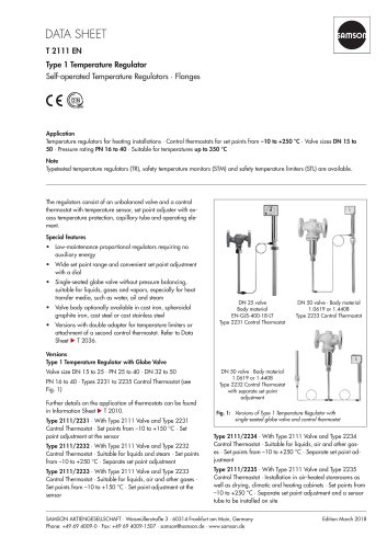
Catalog excerpts
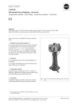
T 2595 EN Self-operated Pressure Regulators · Accessories Compensation chamber · Screw fittings · Control line connection · Control line Application Accessories for Type 41-23 Universal Pressure Reducing Valve, Type 41-73 Universal Excess Pressure Valve, Type 2422/2424 Pressure Reducing Valve and Type 2422/2425 Excess Pressure Valve Various accessories are available for the pressure regulators listed: •• Standard screw joint with restriction G 3/8 For connection of the control line to the actuator. Male thread R ¼, female thread G 3/8 for control line connection, other connections for 6 x 1, 8 x 1, 10 x 1 pipe are possible. Furthermore, Serto (8 x 1, 10 x 1), Swagelok fittings (Ø12, ½”) and ½” NPT screw joints with restrictions are available (see also Screw joints with restriction for Types 2413, 2424 and 2425 Actuators). •• Control line For transmitting the pressure to the operating diaphragm of the regulator. 6 x1 mm pipe with standard screw joint with restriction (standard for DIN versions of regulators) •• Compensation chamber 1) Required for steam or liquids above 150 °C. To collect condensation in applications with vapors and for protection of the operating diaphragm against high temperatures. •• Funnel tube 1) To help fill the diaphragm chamber including the compensation chamber and the control line with the process medium. Fig. 1: Type 41-23 Universal Pressure Reducing Valve with control line The accessories are not included in the scope of delivery and must be ordered separately. SAMSON AKTIENGESELLSCHAFT · Weismüllerstraße 3 · 60314 Frankfurt am Main, Germany Phone: +49 69 4009-0 · Fax: +49 69 40
Open the catalog to page 1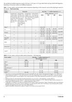
Table 1: Process medium and permissible medium temperature depending on the accessories used and the diaphragm material in the actuator ■ Metal-seated plug The minimum or maximum permissible temperature may be restricted by the valve material. See temperature diagrams in Medium temperatures below 0 °C may cause ice to form on the valve, depending on the air humidity. This may a in particular, the functioning of the stem guide or set point adjuster. This must be prevented on site by taking appropriate precautions (e.g. enclosure, trace heater etc.). Temperature limits for metal-seated plug....
Open the catalog to page 2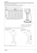
Control line kits Note: Depending on the process conditions, how the pipeline is routed and the adjusted set point, adverse flow conditions may arise at the point of tapping at the body, possibly leading to pressure fluctuations. Therefore, we recommend using an external pressure tapping for a set point lower than 0.8 bar. Control line kit without compensation chamber for Type 41-23 or Type 41-73 Table 3: Control line kit 1) without compensation chamber with order number Nominal size DN Order no. Actuator area 33 cm² Control line kits for direct pressure tapping at a DIN cast body without...
Open the catalog to page 3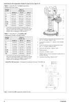
Table 4: Control line kit1 with steel compensation chamber with order number 1) Control line kits for direct pressure tapping at a DIN cast body with compensation chamber, only suitable for standard regulator versions. Other kits avai lable on request (e.g. for actuators with two diaphragms, ANSI valves etc.). 1 Control line between valve body and compensation chamber • 8 x 1 mm pipe • Material 1.4571 2 Compensation chamber 0.7 l • Material 1.4301/S235JR (St 37-2) 3 Control line between actuator and compensation chamber • 6 x 1 mm pipe • Material 1.4571 4 Screw joint with restriction •...
Open the catalog to page 4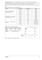
Compensation chamber (see Fig. 4) for welding for Type 41-23, Type 41-73, Type 2422/2424 or Type 2422/2425 If the operating conditions make a compensation chamber necessary, the necessary dimensions and the associated order number must be selected from Table 6 according to the nominal size and dimensions of the actuator (diaphragm area). The control line and the connection pipe are welded to the weld connections of the compensation chamber. They must be provided on site. Table 7: Dimensions • Compensation chambers Fig. 4: Compensation chamber with welding connections
Open the catalog to page 5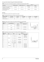
Table 8: Screw joints with restriction for Type 2413 • Standard version and version for oxygen
Open the catalog to page 6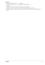
Ordering text –– Compensation chamber, order no. 1190 - … (see Table 6) –– Screw joint with restriction, order no. … (see Table 8, Table 9, Table 10, Table 11) –– Funnel tube –– Control line kit for Type 41-23 and Type 41-73 (for pressure set point ≥0.8 bar) For liquids up to 150 °C, air and gases up to 80 °C, without compensation chamber (see Table 3) For vapors and liquids up to 350 °C, pressure tapping at the valve body, with compensation chamber (see
Open the catalog to page 7
Specifications subject to change without notice
Open the catalog to page 8All SAMSON catalogs and technical brochures
-
TROVIS 5590 Web Module
2 Pages
-
Room Controller TROVIS 5572
2 Pages
-
Room Panel TROVIS 5570
2 Pages
-
Line Splitter TROVIS 5486
2 Pages
-
Type 9 Temperature Regulator
6 Pages
-
Type 8 Temperature Regulator
6 Pages
-
Type 5 D Boiler Controller
2 Pages
-
Rotary Plug Valve Type 62.7
7 Pages
-
Actuator Type S
3 Pages
-
Actuator Type MZ
4 Pages
-
Actuator Type MN
3 Pages
-
Actuator Type MD
3 Pages
-
Actuator Type R
3 Pages
-
Actuator Type AT
4 Pages
-
Rotary Plug Valve Type 82.7
7 Pages
-
Rotary Plug Valve Type 73.7
7 Pages
-
Rotary Plug Valve Type 73.3
7 Pages
-
Rotary Plug Valve Type 72.4
7 Pages
-
Rotary Plug Valve Type 72.3
8 Pages
-
SAMSON Positioners
28 Pages
Archived catalogs
-
T21 11
6 Pages


