- Company
- Products
- Catalogs
- News & Trends
- Exhibitions
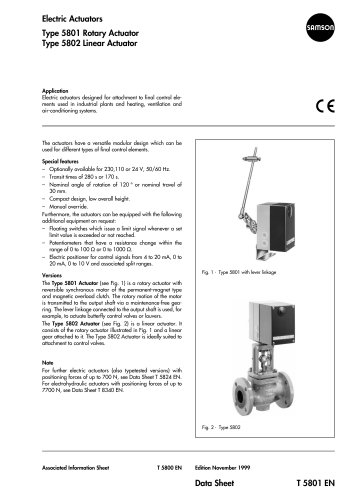
Electric Actuators Type 5821 Type 5822
1 /4Pages

Electric Actuators Type 5821 Type 5822
1 /4Pages
Catalog excerpts
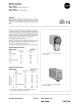
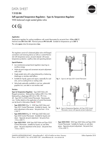
Electric Actuators Type 5821 (without fail-safe action) Type 5822 (with fail-safe action) Application Electric actuators designed for control valves used in heating, ventilation and air-conditioning systems. Form-fit or force-locking mechanical connection between the actuator stem and the valve stem. Type 5821 and Type 5822 Electric Actuators are available in two versions, with form-fit connection between the actuator stem and the valve plug stem or with force-locking connection (see section "versions"). Another physical difference between the two electric actuators mentioned is the manner in which they are attached to the valve body. They are not compatible. The actuators are of the linear type. Type 5821 Electric Actuators come without fail-safe action, Type 5822 Electric Actuators are equipped with fail-safe action. Type 5821 is equipped with a handwheel. For optionally available equipment, refer to Table Technical data. Versions without fail-safe action Electric actuator Travel [mm] Form-fit version Type 5821- I Closing force [N] Versions with fail-safe action Electric actuator Travel Transit time Form-fit version 1) Special version for valves with a minimum reset force of 140 N, e.g. Type 3213 and Type 3214 Globe Valve. Associated Information Sheet T 5800 EN Edition September 1997Data Sheet T 5822 EN
Open the catalog to page 1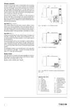
Principle of operation The force of the actuator motor is transmitted to the connecting rod (5) or actuator stem (4) via gear reduction and crankshaft. With form-fit actuator versions, the connecting rod is mechanically connected to the plug stem (20.1) of the control valve. In the other version, the actuator stem presses the plug stem in the closing direction of the valve. Movement in the opposite direction is caused by a spring in the valve. When the final positions are reached, or when the valve is blocked, the motor is disconnected via the torque switches set at the factory. In addition,...
Open the catalog to page 2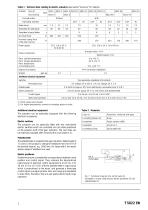
Table 1 ■ Technical data relating to electric actuators (see section"Versions" for details) Additional electrical equipment The actuators can be optionally equipped with the following electrical accessories. Electric switches The actuators can be optionally fitted with two overridable electric switches which are controlled via cam disks positioned on the actuator shaft of the gear reduction. The cam disks can be externally adjusted after removing the cover plate (1.3).
Open the catalog to page 3
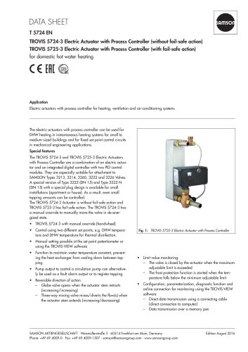
Electrical connection Fig. 8 illustrates the connection diagram of actuators operating without a positioner. The controller output signals are connected to terminals L1 and L2. If voltage is applied to terminal L2, the actuator motor moves the actuator stem (4) or connecting rod (5) in the operating direction "IN" (into the actuator). If, in comparison, a control signal is applied to terminal L1, the connecting rod or actuator stem is moved in the operating direction "OUT". The circuit diagram for versions incorporating electric positioners is depicted in Fig. 9. Control signals from 4 to 20...
Open the catalog to page 4All SAMSON catalogs and technical brochures
 TROVIS 5590 Web Module
2 Pages
 Room Controller TROVIS 5572
2 Pages
 Room Panel TROVIS 5570
2 Pages
 Line Splitter TROVIS 5486
2 Pages
 Type 9 Temperature Regulator
6 Pages
 Type 8 Temperature Regulator
6 Pages
 Type 5 D Boiler Controller
2 Pages
 Rotary Plug Valve Type 62.7
7 Pages
 Actuator Type S
3 Pages
 Actuator Type MZ
4 Pages
 Actuator Type MN
3 Pages
 Actuator Type MD
3 Pages
 Actuator Type R
3 Pages
 Actuator Type AT
4 Pages
 Rotary Plug Valve Type 82.7
7 Pages
 Rotary Plug Valve Type 73.7
7 Pages
 Rotary Plug Valve Type 73.3
7 Pages
 Rotary Plug Valve Type 72.4
7 Pages
 Rotary Plug Valve Type 72.3
8 Pages
 SAMSON Positioners
28 Pages


Archived catalogs
 T21 11
6 Pages


- SAMSON stainless steel valve
- Water valve
- Ball valve
- SAMSON pneumatic valve
- Electrically operated valve
- Threaded valve
- SAMSON regulating valve
- SAMSON flange valve
- On/off valve
- Gas solenoid valve
- Electric valve
- Process software
- Direct-operated solenoid valve
- Gas valve
- Pressure limiter
- Directional control valve
- Pneumatically-operated valve
- Single-stage pressure regulator
- Terminal box