VDP08 and JOYSTICK oem and dealers
1 /116Pages

VDP08 and JOYSTICK oem and dealers
1 /116Pages
Catalog excerpts

Load-Sense Proportional Pressure Compensated Valve Technical Catalogue Company with quality system certied by DNV UNI EN ISO 9001/2008
Open the catalog to page 1
L’Azienda Salami Spa rappresenta un’eccellenza italiana nel settore della potenza idraulica applicata a macchine mobili e veicoli industriali. E’ stata fondata nel 1956 con precise linee guida che hanno condotto il marchio Salami a identicarsi come simbolo di Garanzia e Afdabilità nel proprio settore, in Italia e nel Mondo. Salami Spa è rimasta fedele nel tempo ai tre punti di forza dettati dal suo fondatore che hanno reso riconoscibile e grande il marchio Salami nel mondo: Qualità, Innovazione, Servizio. Attraverso le proprie sedi di Spagna, Francia, Stati Uniti d’America, Canada e ai suoi partner...
Open the catalog to page 3
The Salami Company is one of the best Italian engineering excellences in the eld of hydraulic power applied to mobile applications. It was founded in 1956 with specic guidelines that have led the brand to identify Salami Spa as a symbol of Warranty and Reliability in its sector in Italy and in the World. Salami Hydraulics has remained loyal in time to its three strengths dictated by its founder that have made the brand Salami recognizable and great in the world: Quality, Innovation and Service. Through its ofces in USA, Canada, Spain, France, together with its business partners, it distributes...
Open the catalog to page 5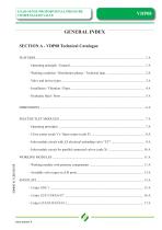
LOAD-SENSE PROPORTIONAL PRESSURE COMPENSATED VALVE
Open the catalog to page 7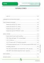
LOAD-SENSE PROPORTIONAL PRESSURE COMPENSATED VALVE GENERAL INDEX
Open the catalog to page 8
LOAD-SENSE PROPORTIONAL PRESSURE COMPENSATED VALVE GENERAL INDEX
Open the catalog to page 9
LOAD-SENSE PROPORTIONAL PRESSURE COMPENSATED VALVE GENERAL INDEX SECTION C - JEC Technical Catalogue
Open the catalog to page 10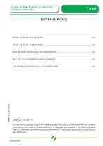
LOAD-SENSE PROPORTIONAL PRESSURE COMPENSATED VALVE GENERAL INDEX E0.003.06.13.14.00IM00 The data on this catalogue refer to the standard product. The policy of Salami consists of a continuos improvement of its products. It reserves the right to change the specications of the different products whenever necessary and without giving any information. If any doubts, please get in touch with our sales department.
Open the catalog to page 11
VDP08 Load-Sense Proportional Pressure Compensated Valve SECTION A - Technical Catalogue
Open the catalog to page 13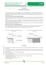
DIRECTIONAL CONTROL VALVE PRESSURE COMPENSATED FEATURES OPERATING PRINCIPLE Load sensing directional control valve VDP08 offers a load-independent ow control (ow in each section depends only by the spool position and not by the load acting on any function), good meetering curves and chance of energy saving. The spool acts as a variable throttling on which the pressure drop is maintained constant, so that each spool position arouses a determinate ow rate. Closed centre version for variable displacement pumps The valve, through the LS signal, sets the pump displacement on the value required by...
Open the catalog to page 15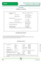
HYDRAULIC FLUID Mineral oil according DIN 51524 Fluid temperature range - 20 + + 85°C MAXIMUM CONTAMINATION LEVEL NAS 1638: class 9 WORKING LIMITS See diagrams PRESSURE DROPS See diagrams For operation with fire resistant fluids, please contact our sales department. There are two characteristic phases in the spool stroke (7 mm - 0,275 in.): a) the overlap phase (about 18% of the stroke) guarantees minimum internal leakages in neutral position; b) the progressive flow regulation phase (82% of the stroke). Oil flow rate portP uptol301/min (34 gpm) Internal leakage at 160 bar (2285 psi) ports A/B...
Open the catalog to page 16
DIRECTIONAL CONTROL VALVE PRESSURE COMPENSATED FEATURES VALVE AND DEVICE TYPES In order to meet the most stringent demands and to offer a wider range of applications, the following types of auxiliary valves and devices are available: · Valves on the inlet Main relief valve - VSLS (see page 7A): controls the maximum pressure in the circuit acting on the LS signal that pilots the ow regulator. Electric unloading valve - EV (see page 9A): if not excited drains the LS signal preventing the valve operation (pump pressure set at the stand-by value 14 bar - 200 psi). Flow regulator (see page 7A): in...
Open the catalog to page 17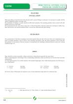
DIRECTIONAL CONTROL VALVE PRESSURE COMPENSATED FEATURES INSTALLATION When proceeding to mount the unit on the structure and to connect ttings to work ports, it is necessary to comply with the values of tightening torques (see page 18A). The attachment of linkages to spools should not affect their operation. The mounting position can be vertical with inlet module on the top or horizontal. We recommend to x the valve always using only 3 of the 4 xing holes, otherwise make sure to interpose 4 rubber insulators between the valve and the machine frame, to avoid valve distorsion and spool sticking....
Open the catalog to page 18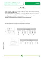
DIRECTIONAL CONTROL VALVE PRESSURE COMPENSATED FEATURES HYDRAULIC FLUID Usually a mineral-base oil with a good viscosity index should be used, preferably with good lubricating properties and corrosion, oxidation and foaming resistant. Sometimes the uids supplied by the manufacturers do not satisfy purity requirements (see WORKING CONDITIONS). It is therefore necessary to lter the uid carefully before lling. Your supplier can give you the information about NAS class of its uids. To maintain the proper purity class, the use of lters of high dirt capacity with clogging indicator is recommended....
Open the catalog to page 19
DIRECTIONAL CONTROL VALVE PRESSURE COMPENSATED DIMENSIONS A/B: working ports P: top inlet port PL:side inlet port T: top outlet port TL:side outlet port LS (see page 8A): load-sensing signal port PG (see page 8A): pressure gauge port The drawing showned is just an example.The overall dimensions you read are valid for all the D.C.V. except the parametric dimensions "L" and "I" depending on the number of working sections.The parametric dimensions "P" depends on a xed dimension of 127 mm (5 in.) to wich you have to had the "X" dimensions that you can nd in the following pages. L I Fixing holes distance...
Open the catalog to page 20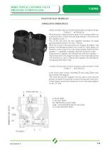
DIRECTIONAL CONTROL VALVE PRESSURE COMPENSATED INLET/OUTLET MODULES OPERATING PRINCIPLES OPEN CENTRE CIRCUIT WITH FIXED DISPLACEMENT PUMP “CODE F” - SEE PAGE 8A When the pump is started and main spools in the working modules are in neutral position, oil ows from the pump through P port across the ow regulator to tank T . The oil ow led across the ow regulator determines the pump pressure(stand-by pressure of 14 bar - 200 psi). When one or more of the main spools are actuated, the highest load pressure is fed through the shuttle valve circuit("LS" pilot gallery, see hydraulic circuit at pag.11A)...
Open the catalog to page 21All SALAMI catalogs and technical brochures
 2PE
2PE42 Pages
 3.5PC_Technical Catalogue
26 Pages
 2PGE_Technical Catalogue
34 Pages
 2ME_Technical Catalogue
28 Pages
 2.5MB_Technical Catalogue
24 Pages
 1.5ME_Technical Catalogue
20 Pages
 3PE and 3ME
53 Pages
 1,5PE
1,5PE41 Pages
 VD10A - VD12A
32 Pages
 GROUP 3.5 - B SERIES
25 Pages
 GROUP 2.5 - B SERIES
29 Pages
 GROUP 2 - E SERIES
35 Pages
 E series
15 Pages
 PG330
PG33034 Pages
 PLC series
11 Pages
 VDP08
VDP0846 Pages
 VDP8
VDP842 Pages
 VDM8 series
38 Pages
 VDM9
VDM922 Pages
 VDM6A series
35 Pages
 VDM6
VDM638 Pages
 VD8A series
48 Pages
 VD6A series
56 Pages
 PG301 series
13 Pages
 H series
33 Pages
 E series
13 Pages
 E series
26 Pages
 B series
32 Pages
 E series
20 Pages
Archived catalogs
 Product range
2 Pages
- Hydraulic pump
- Hydraulic directional control valve
- Spool hydraulic directional control valve
- Hydraulic motor
- Hydraulic gear pump
- Electrically-operated hydraulic directional control valve
- Manual hydraulic directional control valve
- Compact hydraulic pump
- High-pressure hydraulic pump
- Low-noise hydraulic pump
- Aluminum hydraulic pump
- Lever-operated hydraulic directional control valve
- Electro-hydraulic hydraulic directional control valve
- Monobloc hydraulic directional control valve
- Flow divider
- Cast iron hydraulic pump
- Gear hydraulic motor
- Hydraulic flow divider
- CAN Bus joystick