VD10A - VD12A
1 /32Pages

VD10A - VD12A
1 /32Pages
Catalog excerpts

SECTIONAL VALVES Technical catalogue
Open the catalog to page 1
DIRECTIONAL CONTROL VALVE SECTIONAL TYPE Page 1 - GENERAL INDEX Page 2 - Features Page 3 - Features Page 4 - Features - VD10A technical data - VD12A technical data Page 5 - Working conditions - Operating principle Page 6 - Features - Circuit types - Hydraulic fluids Page 7 - Features Page 8 - VD10A - Dimensions from 1 to 8 working modules Page 9 - VD10A - Performance data Page 10 - VD10A - Available inlet and working module types Page 11 - VD10A - End modules - Series circuit spools Page 12 - VD12A - Dimensions from 1 to 8 working modules (standard release) Page 13 - VD12A - Dimensions from 1...
Open the catalog to page 2
Among all hydraulic directional control valves used in the field of mobile equipment applications, the spool valve is the most popular. The sectional valve type allows construction flexibility. Salami directional control valves are modular construction and consist of an inlet section, up to 10 working sections and an outlet section. All these elements are secured in one block by means of tie?rods. Working sections consist of: • a special cast-iron body • a spool with a hardened surface, anticorrosion treated • a device for the operation of the spool • a spool centering device. Salami directional...
Open the catalog to page 3
DIRECTIONAL CONTROL VALVE SECTIONAL TYPE Anti-cavitation check valve on port A or/and B: Avoids cavitation in the system, created by the inertia, when the spool is in neutral position. Port relief and anti-cavitation check valve on port A or/and B: Allows the same functions as the 2 preceding Port relief valve : Limits the working pressure at a lower setting than the principal main relief valve; protects Double-single acting conversion valve : This manual selector changes the working section from double to single acting (A port), Flow limiting valve : Reduces the flow on A and B ports (pressure...
Open the catalog to page 4
DIRECTIONAL CONTROL VALVE SECTIONAL TYPE Nominal flow meaning: flow causing 1 bar (14.5 psi) pressure drop each section, with spools in neutral position Nominal flow from 1 to 8 (for more working modules pis. contact our sales department) In case of series circuit, the values of nominal/max. flow and max pressure are different, Internal leakage For lower leakage please contact our sales department. Spool stroke (positions 1 and 2) Spool stroke (position 4, float or regenerative) *ln case you need the max flow please contact our sales dept. 'For higher back pressure please contact our sales dept....
Open the catalog to page 5
DIRECTIONAL CONTROL VALVE SECTIONAL TYPE WORKING CONDITIONS OPERATING PRINCIPLE Salami directional control valves belong to the 6/3 ( or 6/4 ) type; they can control 6 paths in 3 ( or 4) spool positions simultaneously. They are open circuit types: when the spool is in neutral position, the fluid flows directly to the tank with minimum internal pressure drops (approximatively 1 bar / 14,5 psi for each spool at nominal flow). When the spool is moved from this position, the central path is gradually throttled and the connection between pump and implement, through the corresponding port, is made....
Open the catalog to page 6
DIRECTIONAL CONTROL VALVE SECTIONAL TYPE There are 3 characteristic phases in the spool stroke: - a. the overlap phase (about 38% of the stroke) guarantees minimum internal leakages when it is in neutral position - b. the progressive regulation phase (about 40% of the stroke) allows optimum meetering - c. residual phase (about 22% of the stroke) CIRCUIT TYPES For valve assemblies consisting of two or more working sections, the following types of circuits are avail- Parallel circuit: The spools, when activated simultaneously, will use full system pressure while dividing the available flow by the...
Open the catalog to page 7
DIRECTIONAL CONTROL VALVE X/ninA \/ni9A SECTIONAL TYPE When proceeding io mount the unit on the structure and to connect adaptors to work ports, it is neces- sary to comply with the values of tightening torques as indicated in the maintenance book. The attachment of linkages to spools should not affect their operation, The mounting position can be The contamination of the fluid circulating in the system greatly affects the life of the unit, Above all, contamination may result in irregular operation, wear of seals in valve housings ond failures. Once the initial cleanliness of the system has been...
Open the catalog to page 8
DIRECTIONAL CONTROL VALVE SECTIONAL TYPE DIMENSIONS FROM 1 TO 8 WORKING MODULES L The drawing shown is just an example.The overall dimensions you read are valid for all the VD12A except the parametric dimensions "L" and "I" depending of the number of working sections.The parametric dimension "P" depends on a fixed dimension of 162 mm (6.38 in.) to wich you have to had the "X" and "Y" dimensions that you can find in the spool controls and spool positionings pages. top inlet port I side inlet port top outlet port L side outlet port Weight power beyond port work ports main relief valve(adjustable)...
Open the catalog to page 9
DIRECTIONAL CONTROL VALVE SECTIONAL TYPE Performance curves Internal leakages carried out with A/B -> T 35cm3 /min. (2.14 cu. in./min) Main relief valve P For more information: WWW.SALAMI.IT
Open the catalog to page 10
DIRECTIONAL CONTROL VALVE SECTIONAL TYPE AVAILABLE INLET AND WORKING MODULE TYPES Socket manometer Main relief valve > Inlet with working section Working section Double acting parallel circuit Main relief valve Inlet with hydraulic switch Working section with compensated flow limiting valve For more information: WWW.SALAMI.IT
Open the catalog to page 11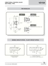
DIRECTIONAL CONTROL VALVE SECTIONAL TYPE Plug closed center circuit Feeding output-downstream user SERIES CIRCUIT SPOOL - FLOAT CIRCUIT SPOOL Double acting spool Double acting spool with float spool position (spool out) For more information: WWW.SALAMI.IT
Open the catalog to page 12
DIRECTIONAL CONTROL VALVE SECTIONAL TYPE DIMENSIONS FROM 1 TO 8 WORKING MODULES RELEASE WITH CAST IRON INLET MODULE + WORKING SECTION (STANDARD) L I VU The drawing shown is just an example.The overall dimensions you read are valid for all the VD12A except the parametric dimensions "L" and "I" depending of the number of working sections.The parametric dimension "P" depends on a fixed dimension of 178 mm (7.01 in.) to wich you have to had the "X" and "Y" dimensions that you can find in the spool controls and spool positionings pages. top inlet port side inlet port top outlet port side outlet port...
Open the catalog to page 13All SALAMI catalogs and technical brochures
 2PE
2PE42 Pages
 3.5PC_Technical Catalogue
26 Pages
 2PGE_Technical Catalogue
34 Pages
 2ME_Technical Catalogue
28 Pages
 2.5MB_Technical Catalogue
24 Pages
 1.5ME_Technical Catalogue
20 Pages
 3PE and 3ME
53 Pages
 1,5PE
1,5PE41 Pages
 VDP08 and JOYSTICK oem and dealers
116 Pages
 GROUP 3.5 - B SERIES
25 Pages
 GROUP 2.5 - B SERIES
29 Pages
 GROUP 2 - E SERIES
35 Pages
 E series
15 Pages
 PG330
PG33034 Pages
 PLC series
11 Pages
 VDP08
VDP0846 Pages
 VDP8
VDP842 Pages
 VDM8 series
38 Pages
 VDM9
VDM922 Pages
 VDM6A series
35 Pages
 VDM6
VDM638 Pages
 VD8A series
48 Pages
 VD6A series
56 Pages
 PG301 series
13 Pages
 H series
33 Pages
 E series
13 Pages
 E series
26 Pages
 B series
32 Pages
 E series
20 Pages
Archived catalogs
 Product range
2 Pages
- Hydraulic pump
- Spool hydraulic directional control valve
- Hydraulic motor
- Hydraulic gear pump
- Electrically-operated hydraulic directional control valve
- Manual hydraulic directional control valve
- Compact hydraulic pump
- High-pressure hydraulic pump
- Low-noise hydraulic pump
- Aluminum hydraulic pump
- Lever-operated hydraulic directional control valve
- Electro-hydraulic hydraulic directional control valve
- Monobloc hydraulic directional control valve
- Flow divider
- Cast iron hydraulic pump
- Gear hydraulic motor
- Hydraulic flow divider
- CAN Bus joystick