PG330
1 /34Pages

PG330
1 /34Pages
Catalog excerpts
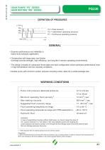
GEAR PUMPS “PG” SERIES GEAR MOTORS “MG” SERIES P3 = Peak pressure P2 = Intermittent operating pressure (1/3 of working time) P1 = Continuous operating pressure max. 20 s GENERAL Superior performance and reliability in heavy-duty hydraulic application. Construction with large area, low-friction bushings provide strength, high efficiency, and long life in severe operating environments. The design includes an advanced thrust plate and seal configuration,which optimizes performance even in high temperature and low viscosity conditions. Double pump with common suction reduces mounting costs, allow for a small package size. WORKING CONDITIONS - Pump inlet pressure (absolute pressure) - Minimum operating fluid viscosity 1 - Suggested fluid viscosity range - Fluid operating temperature range - Fluid operating temperature range with FPM seals(Viton) - Hydraulic fluid Important: in case of assembling of pumps without shaft seals, you have to keep the value of min. suction pressure ( 0.7 bar (abs)) in the vane between pump and coupling too. Lower pressure can lead to suction of oil through the front flange (seat of the shaft without seal); this can damage seriously the pump. 1 - With reduction 80% of working pressure and at minimun speed. Suggestion: to have the best behaviour and duty life of the pump/motor, use a cooling system in order to keep the uid temperature at 60°C and viscosity at 20 cSt.In addition to the recommended ltration index of page 3.
Open the catalog to page 1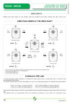
DRIVE SHAFTS Radial and axial loads on the shafts must be avoided since they reduce the life of the unit. DIRECTION VIEWED AT THE DRIVE SHAFT Pump PUMP Pump PUMP Bi - directional rotation Outlet PUMP MOTOR MOTOR Motor MOTOR Motor In case of need we can supply the flange with a threaded hole to vent the drain of the shaft seals area. As you can see on pages 10 and 11, the flanges are: S7 with G1/8 threaded hole S8 with SAE4 threaded hole HYDRAULIC PIPE LINE To ensure favorable suction conditions it is important to keep pressure drop in suction pipe line to a minimum value (see WORKING CONDITIONS)....
Open the catalog to page 2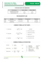
COMMON FORMULAS FOR PUMPS COMMON FORMULAS FOR MOTORS Input flow: Output torque: Output power: Pout = Outlet pressure bar [psi]
Open the catalog to page 3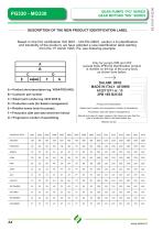
DESCRIPTION OF THE NEW PRODUCT IDENTIFICATION LABEL Based on the firm certification ISO 9001 - UNI EN 29001, section 4.8 (identification and tracebility of the product), we have adopted a new identification label starting from the 1st march 1995. Pls, see following example: Only for pumps 2PB and 2PZ (except triple 2PB) the identification product is marked on the top of the pump body as shown here below: A = Product short descritpion (eg. VD8A/FDD/U4G). B = Customer part number. C = Salami part number (eg. 6235 0025 0). D = Production code (for Salami management) Product short description. Salami...
Open the catalog to page 4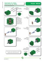
GEAR PUMPS “PG” SERIES GEAR MOTORS “MG” SERIES ROTATION CHANGE INSTRUCTION unscrew and take off the 4 assembling bolts. take off the front ange, complete of shaft seals. take note of the assembling position of the bronze thrust plate. If necessary, you can put a mark which help you remembering the position of the plate related to the body.This is very important, because at the end you must reassemble it in this way. take off the thrust plate. Step 5: take off both the shafts, drive and driven. reverse their position and re-assemble them. reverse and reassemble the front ange. re-assemble the...
Open the catalog to page 5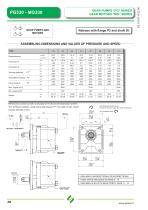
Release with ange P2 and shaft 38 ASSEMBLING DIMENSIONS AND VALUES OF PRESSURE AND SPEED TYPE Dimension B Working pressure Intermittent pressure P2 Intermitten pressure p2 psi Peak pressure Performance carried out with oil viscosity at 16 cSt and oil temperature at 60°C Performance carried out with oil viscosity at 16 cSt and oil temperature at 60°C. Anti-clockwise rotation pump. In case of use as a motor, the same construction *For working conditions, using exclusively pressure P1, the value of max. speed must be reduced of 10%. - AVAILABLE UNI-DIRECTIONAL OR BI-DIRECTIONAL Release with flange...
Open the catalog to page 6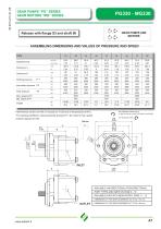
Release with ange S3 and shaft 56 ASSEMBLING DIMENSIONS AND VALUES OF PRESSURE AND SPEED TYPE 23.4 1.43 mm 140.8 in 5.54 Dimension A mm 88 in 3.46 Dimension B bar 260 psi 3800 p2 Intermitten pressure280 bar psi 4000 p3 Peak bar pressure 300 psi 4350 cm /rev Displacement cu.in./rev Dimension A Dimension B Working pressure Intermittent pressure P2 Peak pressure Performance carried out with oil viscosity at 16 cSt and oil temperature at 60°C Performance carried out with oil viscosity at 16 cSt and oil temperature at 60°C. f S °C Anti-clockwise rotation pump. In case of use as a motor, the same construction...
Open the catalog to page 7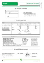
GEAR MOTORS “MG” SERIES WORKING CONDITIONS MG330 MG330 Type max. continuous pressure P 1 max. starting pressure P 2 min. rotational speed max. rotational speed P 1 Motor outlet pressure P out Leakage-oil line pressure P drain TECHNICAL DATA - Minimum operating fluid viscosity 12 mm2 / sec - Permitted viscosity range 12 - 800 mm2 / sec - Recommended viscosity range 20 - 80 mm2 / sec - Permitted viscosity for starting 2000 mm2 / sec - Fluid operating temperature range -20 -15 to 85 °C - Fluid temperature range with FPM seals -20 to 110° C - The standard fluids are all the mineral oil-based corresponding...
Open the catalog to page 8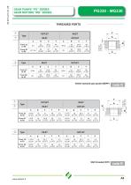
THREADED PORTS British standard pipe parallel (BSPP) GEAR PUMPS “PG” SERIES GEAR MOTORS “MG” SERIES
Open the catalog to page 9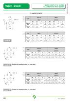
Available for quantity (contact our sales dept.) Available for quantity (contact our sales dept.) GEAR PUMPS “PG” SERIES GEAR MOTORS “MG” SERIES
Open the catalog to page 10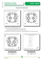
GEAR PUMPS “PG” SERIES GEAR MOTORS “MG” SERIES RELEASE WITH REAR PORTS CLOCKWISE ROTATION PUMP/MOTOR ANTI-CLOCKWISE ROTATION PUMP/MOTOR IN CASE OF USE AS A UNIDIRECTIONAL MOTOR: • ANTI-CLOCKWISE PUMP BECOMES A CLOCKWISE MOTOR CLOCKWISE PUMP BECOMES AN ANTICLOCKWISE MOTOR THE POSITION OF THE PORTS IS THE SAME BUT THE INLET BECOMES OUTLET AND VICEVERSA BI-DIRECTIONAL ROTATION PUMP/MOTOR EXTERNAL DRAIN PORT - DIMENSION C AVAILABLE ALSO WITH DRAIN ON THE SIDE OF THE FRONT FLANGE EXTERNAL DRAIN PORT - DIMENSION C
Open the catalog to page 11All SALAMI catalogs and technical brochures
 2PE
2PE42 Pages
 3.5PC_Technical Catalogue
26 Pages
 2PGE_Technical Catalogue
34 Pages
 2ME_Technical Catalogue
28 Pages
 2.5MB_Technical Catalogue
24 Pages
 1.5ME_Technical Catalogue
20 Pages
 3PE and 3ME
53 Pages
 1,5PE
1,5PE41 Pages
 VDP08 and JOYSTICK oem and dealers
116 Pages
 VD10A - VD12A
32 Pages
 GROUP 3.5 - B SERIES
25 Pages
 GROUP 2.5 - B SERIES
29 Pages
 GROUP 2 - E SERIES
35 Pages
 E series
15 Pages
 PLC series
11 Pages
 VDP08
VDP0846 Pages
 VDP8
VDP842 Pages
 VDM8 series
38 Pages
 VDM9
VDM922 Pages
 VDM6A series
35 Pages
 VDM6
VDM638 Pages
 VD8A series
48 Pages
 VD6A series
56 Pages
 PG301 series
13 Pages
 H series
33 Pages
 E series
13 Pages
 E series
26 Pages
 B series
32 Pages
 E series
20 Pages
Archived catalogs
 Product range
2 Pages
- Directional control valve
- Hydraulic pump
- Hydraulic directional control valve
- Spool hydraulic directional control valve
- Hydraulic motor
- Hydraulic gear pump
- Electrically-operated hydraulic directional control valve
- Manual hydraulic directional control valve
- Compact hydraulic pump
- High-pressure hydraulic pump
- Low-noise hydraulic pump
- Aluminum hydraulic pump
- Lever-operated hydraulic directional control valve
- Electro-hydraulic hydraulic directional control valve
- Monobloc hydraulic directional control valve
- Flow divider
- Cast iron hydraulic pump
- Gear hydraulic motor
- Hydraulic flow divider
- CAN Bus joystick